
LED Driver Circuit with 555 Timer
The LED driver circuit is designed to efficiently power multiple LEDs while maintaining optimal performance and longevity of the components involved. The core of the circuit is typically based on a switching regulator or a simple transistor-based design that enables the control of current flowing through the LEDs.
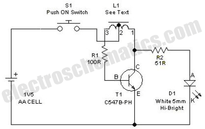
In this configuration, a single NiMH AA cell provides the necessary voltage and current. The circuit may include a resistor to limit the current to the LEDs, ensuring that they do not exceed their rated specifications, which can lead to thermal runaway and eventual failure.
The switching regulator may consist of a transistor, such as an N-channel MOSFET, which acts as a switch that turns on and off rapidly, creating a pulse-width modulation (PWM) effect. This method allows for efficient power management, reducing heat generation and improving battery life.
An additional component, such as a capacitor, may be included in the circuit to smooth out the voltage and provide a stable power supply to the LEDs. This capacitor helps to maintain a consistent brightness level, even when the load changes or the battery voltage drops as it discharges.
The arrangement of the LEDs can be in series or parallel, depending on the desired brightness and forward voltage requirements. If arranged in series, the total forward voltage drop must be considered to ensure it does not exceed the supply voltage. Conversely, if arranged in parallel, each LED should have its own current-limiting resistor to ensure even distribution of current.
Overall, this LED driver circuit exemplifies a practical application of basic electronic components to achieve efficient and effective illumination solutions using minimal power resources.This simple LED driver circuit allows us to drive up to seven LEDs by using a single NiMH (Nickel Metal Hydride) AA cell. The circuit produces voltage puls.. 🔗 External reference
Related Circuits

The preamplifier circuit is designed to offer appropriate loading for phono cartridges with reluctance. It achieves a gain of approximately 25 dB at 1 kHz (converting an input of 2.2 mV to an output of 100 mV). The circuit...
This circuit generates a two-tone effect similar to the cuckoo song. It can be utilized for doorbells or other applications due to its integrated audio amplifier and loudspeaker. As a sound effect generator, it can connect to external amplifiers,...

The IR Theremin hardware schematic is notably simple, as the primary input and output devices require minimal connections. This simplicity can be a double-edged sword, as fewer hardware components often lead to increased software complexity. The main components utilized...
This radio receiver can operate with any of the following transistors: ZN414, MK484, or TA7642. The radio receiver circuit is designed to utilize a variety of transistors, specifically the ZN414, MK484, and TA7642, which are commonly used in low-power AM...
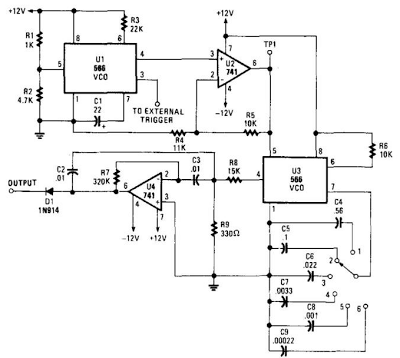
When this circuit is connected to a filter and an oscilloscope, the oscilloscope displays the filter's frequency response. A frequency that sweeps from low to high is applied to a filter. The oscilloscope is triggered by the start of...

This circuit is a conventional Pierce-type oscillator that utilizes a JFET. It operates with fundamental mode crystals, offering decent performance and reliability when a low noise JFET is employed. The feedback is regulated by the capacitance of C1 from...