
Arduino 2-axis servo solar tracker
The described circuit involves a servo mechanism controlled by light and tilt sensors, forming a basic automated tracking system. The servo armature is essential for adjusting the angle of the mirror based on sensor inputs. The light sensors detect ambient light levels and guide the servo to orient the mirror towards the light source, enhancing the system's responsiveness to environmental changes. The tilt sensor plays a critical role in preventing the mirror from tilting too far down, which could lead to mechanical failure or misalignment.
In terms of wiring, the use of a ribbon cable simplifies connections to the breadboard, allowing for easy adjustments and troubleshooting. The application of insulating materials is crucial for maintaining circuit integrity, as exposed wires can lead to short circuits, especially in an environment where movement occurs. The sensors are strategically placed to maximize their effectiveness, ensuring that they can adequately detect light from various angles.
The choice of components, such as the type of light sensors and the tilt sensor, can significantly affect the performance of the circuit. Substituting different sensors may require modifications to the code that processes the sensor inputs, indicating the importance of software-hardware integration in the design. The overall assembly should be tested to confirm that the sensors function correctly and that the servo responds accurately to their signals, providing a reliable tracking mechanism.I marked the approximate center of the base and drilled a hole large enough to screw the setscrew for the servo armature in. I then hot glued the armature to the underside of the base making sure not to get glue in the hole i drilled.
I used 3 light sensors and 1 tilt sensor. You can substitute LEDs orphoto-transistors for the CDS cells, and/or me rcury switches for theball bearing tilt sensor but your code will have to reflect the change(s). I soldered wires from a scrap ribbon cable to the leads of each light sensor and a 2 pin header on the opposite end to connect easily to the breadboard. Use electrical tape / heat shrink / liquid insulator on the bare parts of the wire so that they don`t short out.
Once that`s done, hot glue the sensors at equal intervals around the circumference of the mirror. I placed the sensors so that the flat collecting side of the sensor was parallel with the plane of the mirror and angled out from the center just slightly. The tilt sensor that I found was a plastic box with 4 contacts running through it and a ball bearing inside.
This sensor prevents the tracker from pointing at the ground and also gives the y-axis an end-stop. Solder wires onto the 4 pins of the tilt sensor then glue it on the back side of the mirror with the leads running horizontally. With the mirror pointing straight upward, the BB should be resting on the 2 middle leads. 🔗 External reference
Related Circuits
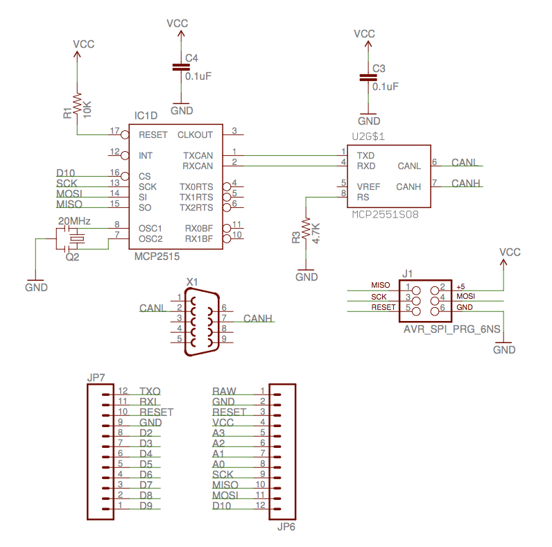
The implementation of the Controller Area Network (CAN) for aircraft applications is referred to as CAN-FIX, which is part of the MakerPlane Open Source Airplane project. This project aims to create an Arduino shield that facilitates communication over the...
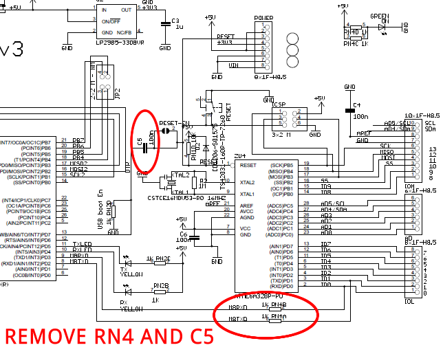
The Arduino Uno is a simple modification that bypasses the USB circuitry, allowing the device to be programmed using a serial port. The Arduino Uno is a widely used microcontroller board based on the ATmega328P microcontroller. It is designed to...
Savings on electricity bills can be achieved by utilizing alternative power sources. The photovoltaic module or solar panel described here has a power output of 5 watts, providing 16.5V under full sunlight conditions, with a current delivery of 300-350...
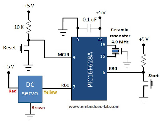
A servo motor is a specialized geared DC motor that includes an electronic circuit for controlling the direction and position of the motor shaft. Due to its capability for precise angular positioning, servo motors are widely utilized in robotics,...
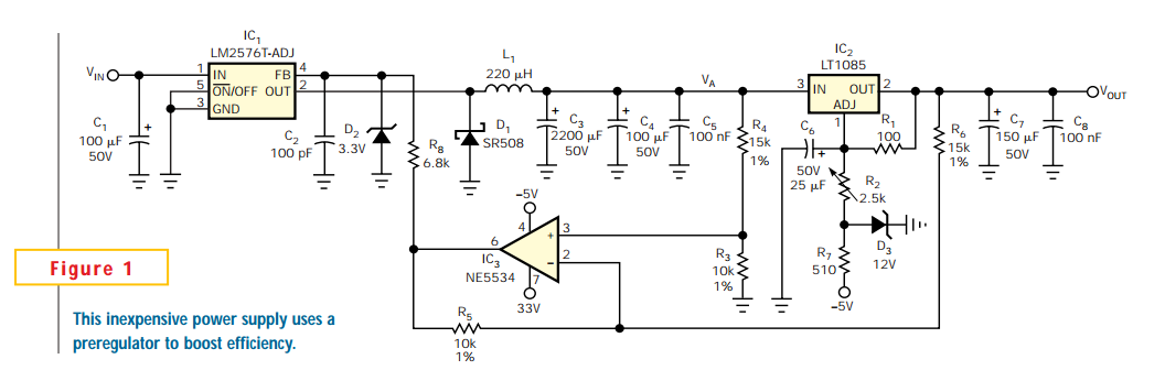
Linear regulators are easy to implement and have better noise and drift characteristics than switching approaches. Their largest disadvantage is inefficiency: excess energy dissipated as heat. Several well-known techniques are available to minimize the input-to-output voltage across a linear...
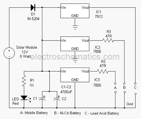
An effective solution for harvesting solar energy for charging purposes. This charger can replenish almost all types of batteries, including mobile phone batteries. It utilizes a solar module to convert light energy into electrical energy. The circuit is self-explanatory....
Warning: include(partials/cookie-banner.php): Failed to open stream: Permission denied in /var/www/html/nextgr/view-circuit.php on line 713
Warning: include(): Failed opening 'partials/cookie-banner.php' for inclusion (include_path='.:/usr/share/php') in /var/www/html/nextgr/view-circuit.php on line 713