
Servo motor control
The servo motor's operation relies on feedback control to ensure accurate positioning. The internal components include the DC motor, gears, a potentiometer for feedback, and a control circuit that processes the PWM signal. The potentiometer provides continuous feedback on the shaft's position, enabling the control circuit to make real-time adjustments to the motor's operation. The PWM signal, which varies in width, effectively communicates the desired angle to the servo. As the PWM signal changes, the control circuit interprets these changes and drives the motor accordingly to achieve the specified position.
In practical applications, the interfacing of a servo motor with a PIC microcontroller is accomplished through a simple circuit. The control pin of the servo is connected to a designated output pin on the PIC microcontroller, which generates the PWM signal. The microcontroller can be programmed to produce varying pulse widths based on user input or sensor data, allowing for dynamic control of the servo's position. The power supply connections are made to ensure the servo receives the appropriate voltage for operation, while the ground connection provides a common reference point for the circuit.
In summary, the servo motor is a versatile component widely used in various applications requiring precise motion control. Its integration with microcontrollers allows for sophisticated control mechanisms in robotics and remote-controlled devices, making it an essential element in modern electronic design.A servo motor is a special geared DC motor equipped with an electronic circuit for controlling the direction of rotation, as well as the position, of the motor shaft. Because servo motors allows precise angular positioning of their output shaft, they are used extensively in robotics and radio-controlled cars, airplanes, and boats to control the mo
tion of their various parts. In this lab session, we will first explore what a servo motor consists of and how it works and then illustrate how to interface it with a PIC microcontroller. A servo motor (or servo) is a little box that contains a DC motor, an output shaft (servo arm) which is connected to the motor through a series of gears, and an electronic circuit to control the position of the shaft.
The objective of using a servo is to achieve precise angular positioning of an object. In order to accomplish a servo function, an instantaneous positioning information of the output shaft is fed back to the control circuit using a transducer. A simplest way of doing this is by attaching a potentiometer to the output shaft or somewhere in the gear train.
The control electronics compares the feedback signal (which contains the current position of the shaft) from the potentiometer to the control input signal (which contains information of the desired position of the shaft), and any difference between the actual and desired values (known as an error signal) is amplified and used to drive the DC motor in a direction necessary to reduce or eliminate the error. The error is zero when the output shaft gets to the desired position. The functioning block diagram of a typical servomotor is shown below. The control input to a servo is a pulse width modulated (PWM) signal, generally of frequency 50 Hz. This means the pulse should repeat every 20ms. The width of the pulse determines the angular position of the output shaft. An electronic circuit inside the servo converts the PWM signal to a proportional output voltage which is compared with the feedback voltage from the potentiometer.
If a difference exists between the two, the control circuit drives the motor in an appropriate direction until the difference becomes zero. A typical value of the pulse width is somewhere in the range of 1. 0 to 2. 0 milliseconds (ms). For a standard servo, a pulse width between 1. 0 ms to 1. 5 ms makes the servo to turn clockwise (CW), between 1. 5 ms to 2. 0 ms makes it to turn counterclockwise (CCW), and a 1. 5 ms pulse width turns the servo motor to its center. However, these values could vary depending on the brand and make of the motor. It is advised to read the datasheet of the servo to find the true values of the pulse widths required for positioning the servo at different angles.
Most servos rotate through 180 °. However. there are some that could rotate through a full 360 ° or more. Servos are widely used as the moving joints in robotic arms for their precise angular positioning. They also finds applications in radio controlled (RC) toys. For example, in RC cars they are used in the steering mechanisms, and in RC boats to control the rudder. A servomotor has three wires: two are designated for power supply (Vcc and Ground) and the third wire is for the control signal.
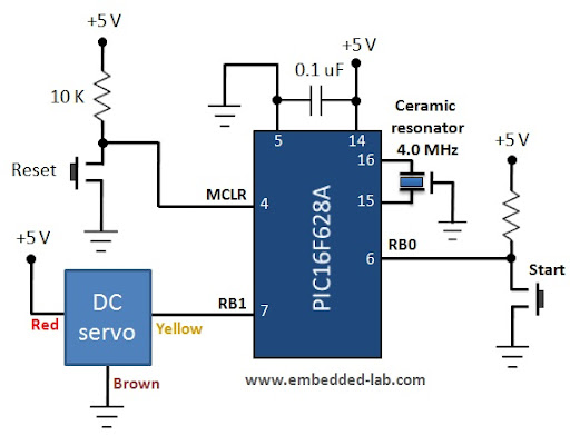
The Vcc wire is usually red and the ground one is either black or brown. Thecontrol signal wire comes in white, yellow, or orange color. The servomotor used in this experiment is from iCircuit technologies and has red, brown, and yellow color wires for Vcc, Gnd, and control signal, respectively. It operates at 5. 0 V power supply and provides angular rotation through 180 ° The pulse width values for different angular positions of this servo are provided in the table below.
Remember that the repetition rate of the pulse should be 50 Hz (period of 20 ms). The circuit diagram of this experiment is depicted below. The control input for the servo is derived from the RB1 pin of the PIC16F 🔗 External reference
Related Circuits

Traditional control methods for fan power equipment involve manual or relay control, which often leads to issues of poor reliability and flexibility. For instance, when the motor capacity is large, the startup process can be prolonged, resulting in high...

A voltage-controlled oscillator (VCO) is an electronic signal generator that produces a signal with a variable frequency, which is dependent on an input voltage level. A voltage-controlled oscillator is a fundamental component in various electronic applications, including phase-locked loops (PLLs),...
The motor is utilized to provide the mechanical output of the system and to move the potentiometer for loop closure. For high-power servos, three-phase motors can be employed. Potentiometer: A simple potentiometer can be used for standard industrial applications...

The circuit diagram illustrates a group of four analog electronic circuit switches (S1 to S4). Switches S1, S2, and S3 are utilized in a parallel delay circuit. When the power is activated, resistor R4 drives the triac VT, which...
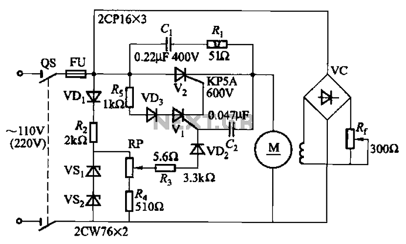
A 100W resistance-triggered motor control circuit designed for arc welding machines. It features an adjustment potentiometer (Rr) that can modify the DC motor excitation current. Additionally, a regulator (RP) is included to adjust the DC motor armature voltage, enabling...
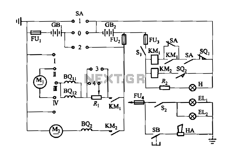
Denote cam controller SA 1 contact closure case. M1 is 1.35 kW driving motor, M2 is a 4 kW pump motor. The circuit involves a cam controller designated as SA 1, which is responsible for managing the operation of...