
Arduino and ATMega8

The programming jig serves as a dedicated platform for programming AVR microcontrollers, providing a stable and reliable environment that enhances the programming process. This jig typically includes a socket for the microcontroller, ensuring proper alignment and secure connections, which reduces the risk of errors that may occur when using a breadboard.
Key components of the programming jig may include a power supply circuit to deliver the appropriate voltage levels required by the microcontroller, as well as interface connections for programming signals. The design should incorporate decoupling capacitors near the power pins of the microcontroller to filter out any noise that could interfere with programming.
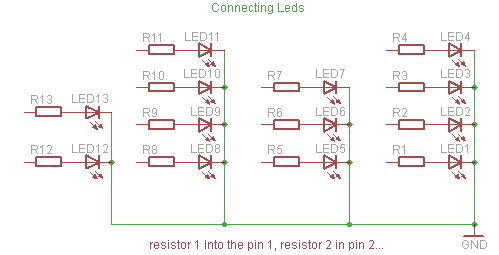
Additionally, the jig may feature indicator LEDs to provide visual feedback on the programming status, such as power on, programming in progress, and completion. The layout should be optimized for minimal interference and ease of access to programming pins, facilitating quick and efficient programming cycles.
For enhanced functionality, the jig can be designed to accommodate multiple microcontroller types by using interchangeable sockets or adapters. This versatility makes it a valuable tool for developers working with various AVR models.
Overall, the programming jig represents an important advancement in the development process, streamlining programming tasks and improving the reliability of circuit testing and development.I have since constructed a programming "jig" to avoid keeping the circuit on the breadboard. More detail, and photographs can be found on the Learning About the AVR Parallel Programmer page. 🔗 External reference
Related Circuits
A simple timer that can be used to turn a load on or off after a user-specified time. The prototype was developed using the xBoard MINI, a low-cost and easy-to-use ATmega8 development board. The program was burned to the...
Yesterday, a decision was made to abandon watching a movie in favor of building a binary clock. After some contemplation on the programming aspect, the project was successfully completed. The clock operates effectively, and a detailed explanation of the...
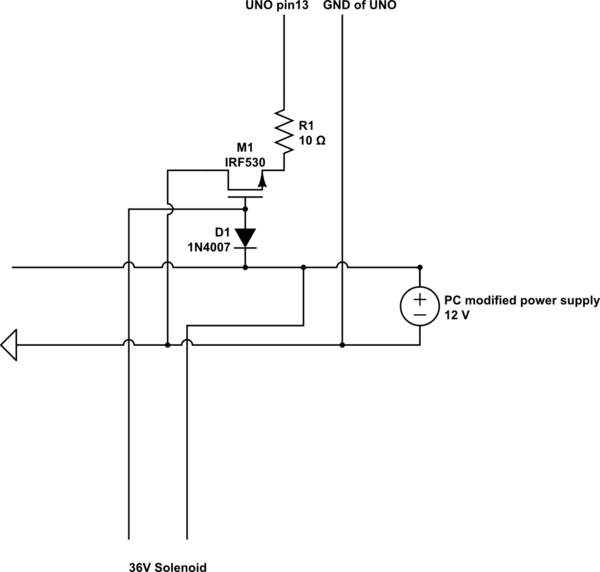
A 9 V DC battery initially powered the solenoid valve effectively. However, the solenoid did not generate sufficient force due to inadequate DC power. A modification was made to use a computer power supply as the power source. Providing...
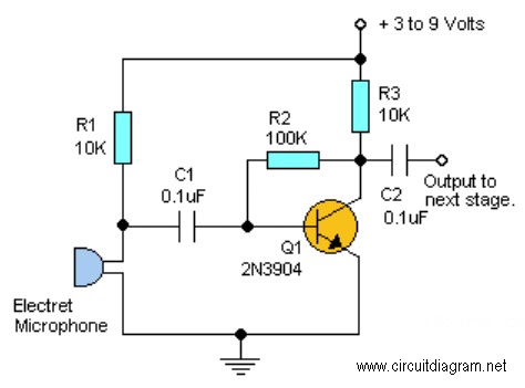
This project requires expensive hardware, including a microphone and amplifier, along with sophisticated audio analysis on the microcontroller. Even a complete microphone with an amplifier circuit does not yield the desired results, as noted in the product comments. The...
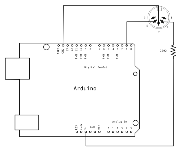
MIDI, or Musical Instrument Digital Interface, is a protocol designed for controlling synthesizers, sequencers, and various musical devices. MIDI devices are typically categorized into two main classes: controllers, which generate MIDI signals based on user input, and synthesizers, which...
Make your own Guitar Effects Pedal with an Arduino board. Bit crushing, rate reducing, weird noises. 10-bit effects/guitar pedal with an Arduino for lo-fi DSP The project involves designing a guitar effects pedal utilizing an Arduino microcontroller to create various...