
Relay Timer with ATmega8 AVR MCU

The Simple Device Timer circuit employs an ATmega8 microcontroller, which serves as the core processing unit. The ATmega8 is a versatile 8-bit AVR microcontroller featuring 8 KB of flash memory, 1 KB of SRAM, and 512 bytes of EEPROM, making it suitable for various applications, including timing and control tasks. The xBoard MINI development board provides a convenient platform for prototyping, integrating essential components like power supply, crystal oscillator, and programming interface.
The timer's user interface is facilitated by a 16x2 LCD module, which displays the countdown timer and allows users to interact through a 3-button keypad. The keypad typically consists of three buttons: one for increasing the time, one for decreasing it, and one for starting the timer. The microcontroller reads the button presses through its digital input pins, enabling user input to adjust the timing parameters.
The countdown functionality is implemented through an interrupt-driven approach, where the microcontroller utilizes its internal timers to keep track of elapsed time. Once the user sets the desired time and starts the timer, the program enters a loop that continuously updates the LCD display with the remaining time. When the countdown reaches zero, the microcontroller activates a relay or transistor to turn off the connected load, ensuring that the device operates only for the specified duration.
The use of the avr-gcc compiler and AVR Studio for development allows for efficient programming and debugging of the microcontroller, ensuring reliable operation of the timer. The inclusion of an LCD driver library simplifies the process of controlling the LCD module, enabling smooth updates to the display without extensive coding overhead. Overall, this Simple Device Timer project exemplifies an effective application of microcontroller technology in creating user-friendly timing solutions.A simple timer that can be used to turn on/off a load after user specified time. The prototype was developed using xBoard MINI, a low cost easy to use ATmega8 development board. The program was burned to the MCU`s flash memory using eXtreme Burner - AVR Software and Hardware. The Simple Device Timer project designed using ATmega8 AVR MVU. The Timer is usefully for keeping a device "ON" for a specific period of time. After the set time elapse the timer automatically turns the load off. The Timer uses a standard 16x2 lcd module for user interface UI. User can set the time using a 3 button keypad. After that Timer is started. While count down is in progress, the time left is displayed on screen. The program use our LCD driver library more details of which can be found in Web site. Use avr-gcc + AVR Studio to compile. 🔗 External reference
Related Circuits
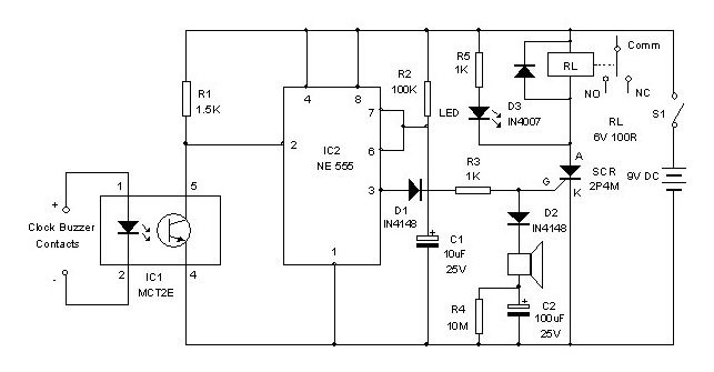
This timer is designed primarily to turn off a portable radio after a set duration. This feature allows users to relax on the beach or in a hammock, confident that the device will automatically power down after a specified...
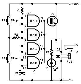
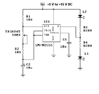
A practical and engaging project involving a flip-flop relay circuit utilizing a 555 integrated circuit (IC). This circuit will continuously toggle two relays on and off in succession. The flip-flop relay circuit using a 555 IC is designed to alternate...
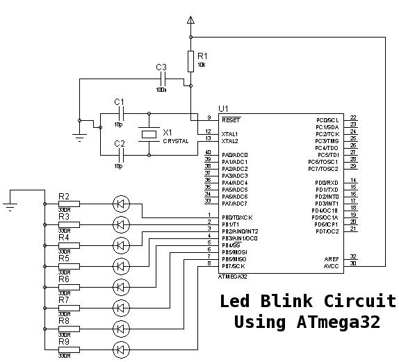
This is a basic tutorial for beginners using the ATmega32 microcontroller to get started. This program can be referred to as a "Hello World" for the ATmega. The ATmega32 microcontroller is a member of the AVR family, widely utilized in...
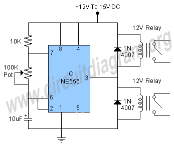
A clock-controlled relay, also known as a time delay relay, allows for the automatic activation of a load, such as a water pump, at a predetermined time. This device utilizes a standard clock mechanism to trigger the circuit, enabling...

The line is intentionally not straight to test its performance with zig-zags and splits, which are common in the Chibots advanced line-following contest. The AVRcam is a compact, real-time image processing engine designed to track colorful objects. This system...
This is a simple LED flasher project that utilizes a common 555 timer integrated circuit (IC) for its operation. It is configured in astable mode, which means its output functions as a square wave oscillator. Two LEDs are connected...