
Arduino Audio Output
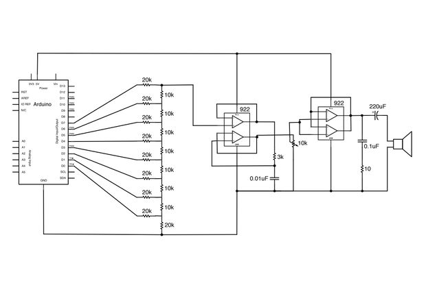
To create a digital-to-analog converter (DAC) using an Arduino, one can utilize the Pulse Width Modulation (PWM) feature available on many Arduino boards. PWM allows the microcontroller to simulate an analog output by varying the duty cycle of a digital signal. This method is particularly useful for generating audio signals or controlling the brightness of LEDs.
The basic setup involves connecting a low-pass filter to the PWM output pin of the Arduino. The filter, typically composed of a resistor and capacitor, smooths the PWM signal into a more stable analog voltage. The resistor (R) and capacitor (C) values can be selected based on the desired cutoff frequency, which determines how effectively the PWM signal is filtered. A common configuration might use a resistor of 1k ohm and a capacitor of 10µF, resulting in a cutoff frequency of approximately 15.9 Hz.
To implement this, the Arduino can be programmed to output a PWM signal using the `analogWrite()` function. This function takes two parameters: the pin number and the value (ranging from 0 to 255) that corresponds to the desired voltage level. For example, a value of 127 would yield approximately half of the supply voltage, while a value of 255 would output the maximum voltage.
In addition to audio applications, this DAC setup can also be employed for various control tasks, such as adjusting the speed of motors or the brightness of lights. By modifying the duty cycle of the PWM signal, the output voltage can be finely tuned to meet the requirements of the specific application.
Overall, this basic DAC configuration using an Arduino provides a simple yet effective means of generating analog voltages from digital signals, expanding the versatility of the microcontroller in various electronic projects.Generate sound or output analog voltages with an Arduino. This Instructable will show you how to set up a really basic digital to analog converter so.. 🔗 External reference
Related Circuits
This circuit can be used to remotely monitor a loudspeaker, alarm, or audio source for presence of an audio waveform. It can also be directly connected across loudspeaker terminals used as a peak indicator. If you need to monitor...
The first reverberator presented is based on the TDA1022, which is the most commonly used BBD (Bucket Brigade Device). Adjustments for proper functionality of the reverberator are required before connecting the power supply. The TDA1022 is a versatile BBD that...
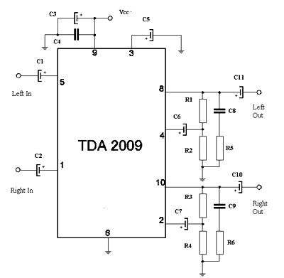
The circuit features a Class AB audio amplifier integrated circuit (IC) that necessitates only a minimal number of external components. This series is straightforward to construct. The 10W stereo amplifier circuit requires a stable power supply with a voltage...
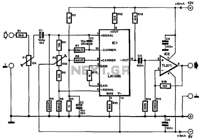
Often, the frequency of a signal must be doubled, and the modulator/demodulator chip LM1496 serves as an ideal basis for this application. From trigonometry, it is well known that 2sin(x)cos(x) = sin(2x) and sin^2(x) = 1 - cos^2(x). These...
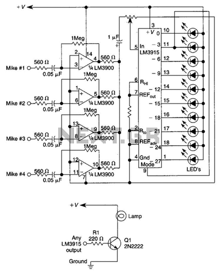
This circuit will produce an output when the sound exceeds a preset level. The LM3915 is a log-output bar graph driver. A transistor driver is used for higher current loads. To drive heavy-current loads with an LM3915 output, a...
This circuit combines two or more audio channels into a single channel (for example, mixing stereo into mono). The design allows for the addition of multiple channels, consuming minimal power. Although the schematic illustrates two inputs, it is possible...