
Arduino Controls an Infrared Helicopter
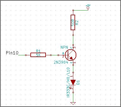
The 2N3904 NPN transistor is a widely used component in electronic circuits, particularly for switching and amplification applications. In this configuration, it serves as a switch to control the operation of an infrared (IR) LED. The circuit operates with a +5V supply from an Arduino board, which is a common platform for prototyping electronic projects.
The Emitter (pin 1) is connected to ground, while the Base (pin 2) is driven by a control signal from the Arduino, allowing it to turn the transistor on and off. When the Base receives a high signal (typically 5V), it allows current to flow from the Collector (pin 3) to the Emitter, thus powering the IR LED connected in series with the 50 Ohm resistor.
The choice of a 50 Ohm resistor is critical to protect the IR LED from excessive current. Given that the IR LED has a maximum forward current rating of 100 mA, the resistor ensures that the current is limited to a safe level when the LED is powered. The calculation for the resistor value, R = V / I, confirms that a 50 Ohm resistor will limit the current to 100 mA when a 5V supply is applied. However, a 47 Ohm resistor, which is more readily available, can also be used as a substitute, providing similar current limiting characteristics while remaining within safe operational limits for the IR LED.
In summary, the circuit effectively utilizes the 2N3904 transistor to control an IR LED with appropriate current limiting, ensuring reliable operation and protection for the LED component.2N3904 is the NPN transistor. Looking at the flat face, the left lead is Emitter (pin 1 in schematic), the middle lead is Base (pin 2 in schematic), the right lead is Collector (pin 3 in schematic). Another end of 50 Ohm resistor to +5v pin on Arduino. (An alternative would be use a bigger resistor, say 100 Ohm, to replace the 50 Ohm one, and conn ect the other end to Vin Pin on Arduino. ) This resistor is to make sure we won`t burn the IR LED. The IR LED can only accept a maximum of 100 mA current, so if we use 5V to drive the IR LED, we need to make sure the current running through the LED is limited to less than 100 mA, which yields the resistance R=5V/100mA=50 Ohm. The nearest commonly-found resistor is 47 Ohm. 🔗 External reference
Related Circuits
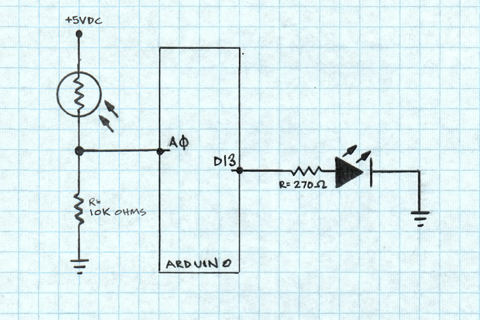
A project is underway to determine the number of sun hours available at a specific location and to track this data over time as part of solar power installation design. The concept involves utilizing a light detector exposed to...
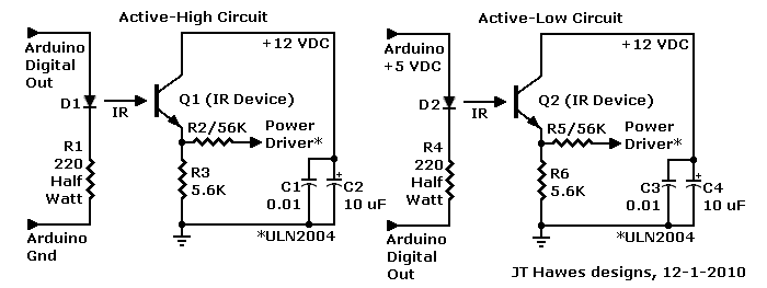
A Darlington transistor can enhance circuit performance, although it introduces slight complexity. The advantage of using a Darlington configuration lies in its capability to achieve low output impedance. The recommended component is the 2N6426 from Mouser, with alternatives such...
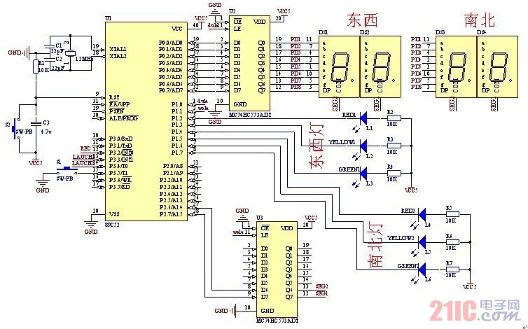
A steady, flexible, and convenient traffic light control system is essential for effective traffic management. In practice, many traffic lights operate on a time interval basis. This design allows for the adjustment of switching times for traffic lights during...
A programming jig has been constructed to eliminate the need for maintaining the circuit on a breadboard. Additional details and photographs are available on the Learning About the AVR Parallel Programmer page. The programming jig serves as a dedicated platform...
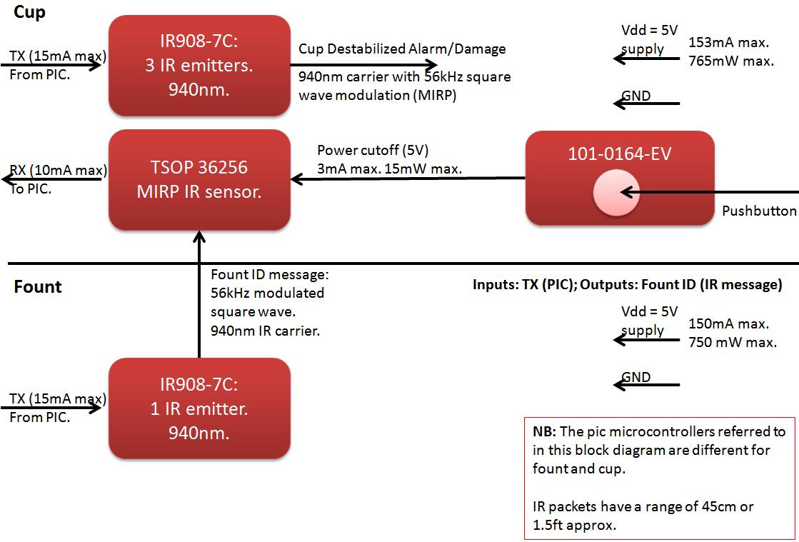
The founts must notify the server when the cup is taken from the fount or when the opponent's cup is poured into the team's cup. The implementation of the actual pouring action is at the discretion of the team....
Modern ICON electronic engine controls from BRP The ICON electronic engine control system developed by Bombardier Recreational Products (BRP) represents a significant advancement in marine technology. This system integrates sophisticated electronic controls to enhance the performance and reliability of marine...