
Arduino multi-mode lamp with soft touch switch

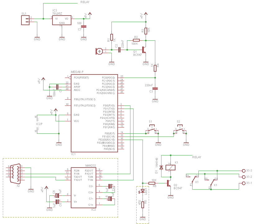
The circuit design focuses on integrating the ATMega-328 microcontroller, which serves as the central processing unit for controlling the light displays. The microcontroller interfaces directly with the RGB LEDs, allowing for dynamic color changes and effects. The common-anode configuration of the RGB LEDs necessitates careful selection of resistor values to ensure proper current limiting for each color channel, preventing damage to the LEDs. The touch bar is implemented using a capacitive touch sensing technique, where the microcontroller detects changes in capacitance when a finger approaches or touches the sensor area. This allows for a user-friendly interface to switch between different lighting modes.
The development process includes setting up the Arduino IDE for programming the ATMega-328. The software handles the logic for each lighting effect, utilizing timers and interrupts to manage the timing of light changes based on user input from the touch sensor. The circuit's minimalist design not only reduces costs but also simplifies assembly and troubleshooting. The incorporation of Teflon wire enhances the reliability of the connections, particularly in compact spaces where heat may be a concern.
Overall, this project exemplifies a cost-effective approach to creating an interactive lamp with multiple lighting options, leveraging the capabilities of the Arduino platform and the flexibility of the ATMega-328 microcontroller. The thoughtful selection of components and design considerations ensures a functional and engaging user experience.In this Arduino-based project, we will build a lamp with multiple light displays: color sequencer, dimming light, color chaser, firelight all selected by a touch bar on the circuit board. We will be going the minimalist way for this project, filling the board with just a microchip, the LEDs, a handful of resistors and some capacitors, all for
under $10, along with the necessary connecting hardware. The circuit will be using 3 RGB LEDs. These arecommon-anodePiranha type available here and contains three LEDs within its body. Each color will need a single dropping resistor (220-ohm for green and blue and 330-ohm for Red). We can also add a small LED with a 1k-ohm as an indicator. The IC we are using is an ATMega-328 microchip, available for about $5 here You will also need a 16Mhzresonatorfor about 35c, also available at the same site. The development and testing of the software is done using the Arduino system, so a suitable host` is necessary.
I`ve used an Arduino Nano`, a Boarduino and a RBBB board and they all work fine. It is averygood idea to put the microchip in a socket. Here, I`ve used 2 x 16-pin sockets end-to-end, because that is what I have available The ATMel chip only has 28-pins so we`ll have a few empty sockets on the end. After I`ve done the preliminary wiring, the circuit (and programming) is tested through jumpers connected to the host`, an RBBB (Really Bare Bones Board), also from Modern Devices.
This lets me make sure the wiring is correct before we commit the Microchip. A major effort-saver is the use of Teflon wire, which does not melt even when routed close to soldered parts. Teflon wire is also available silver-plated which allows me to use thinner wires (#28) and still handle the current.
These wires can be found here on eBay. The wiring at the front is used as the touch sensor. The program measures the voltage drop between the wires and can tell if it is touched. The duration is measured and we can tell if it is a tap, a press or a hold, and the program uses it to control the light patterns. 🔗 External reference
Related Circuits

This circuit requires the bridging of two circuits to activate the electronic switch. It does not require a 60-Hz field to operate and can be powered by either battery or AC. The two pickup terminals can be made from...
For those who prefer convenience, it is possible to turn the bedroom light on or off without leaving the bed simply by clapping hands. This concept inspired the design of a clap-activated light control system. Various clap switch projects...

This is a low voltage, high-current output switching DC power supply with an input of 220 volts AC. In this circuit, an ST2 DIAC relaxation oscillator, Q3, C1, and the DIAC initiate conduction of the output switching transistor Q1....
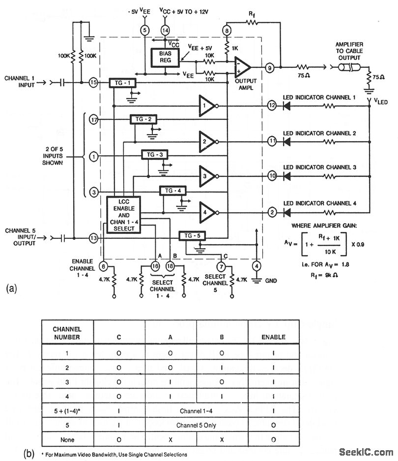
This circuit illustrates a CA3256 switch/amplifier configured for a direct-coupled output. One of four channels can be selected in parallel with channel 5. The analog switches of channels 1 to 4 are digitally controlled by logic. A VEE of...

This power supply utilizes an SGS-Thomson UC3842 integrated circuit in an off-line flyback regulator configuration, delivering +5 V at 4 A and ±12 V at 300 mA. This design allows for the use of a compact high-frequency (50 kHz)...
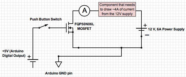
If the ground of the Arduino is disconnected from the negative terminal of the power supply, current flows through the MOSFET, even when the switch is not closed. In an electronic circuit involving an Arduino and a MOSFET, maintaining a...