
Analog video switch and amplifier with direct coupled output
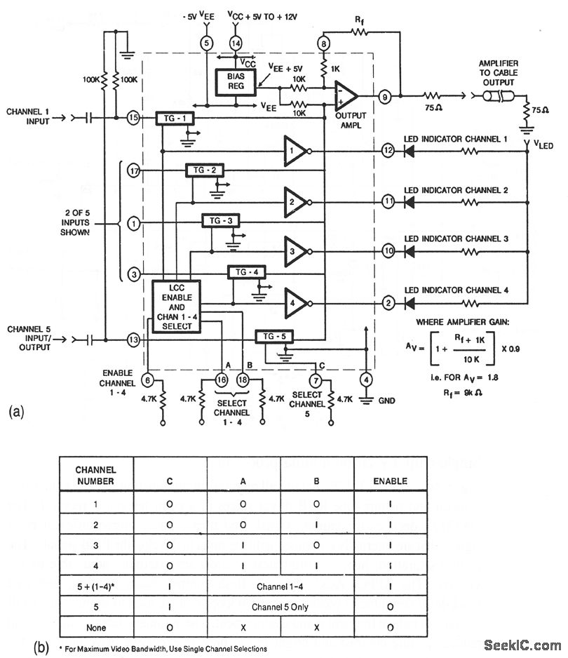
The CA3256 circuit is designed to provide flexible switching and amplification capabilities across multiple channels. It features a direct-coupled output, which enhances the fidelity and speed of signal transmission, making it suitable for applications where minimal signal distortion is critical. The ability to select one of four channels in parallel with channel 5 allows for versatile signal routing, accommodating various configurations depending on the application requirements.
The digital control of the analog switches for channels 1 to 4 is implemented using a logic circuit, enabling precise selection and operation of the desired channel without the need for mechanical switches. This digital approach enhances reliability and reduces wear over time, which is particularly beneficial in applications requiring frequent channel switching.
Power supply requirements for this circuit stipulate a negative voltage (VEE) of -5 V, which is essential for proper operation of the CA3256 device. The positive supply voltage (Vcc) can be adjusted between +5 V and +12 V, allowing for compatibility with a range of systems and ensuring that the amplifier can operate efficiently within its specified limits.
The gain of the amplifier is adjustable through the use of an external feedback resistor (Rf). The relationship between the feedback resistor and the gain can be described by the appropriate gain equation, which should be referenced for accurate calculations. This feature provides flexibility in signal amplification, enabling the circuit to be tailored for specific signal levels as required by the application.
Overall, this circuit design offers a robust solution for applications requiring channel switching and amplification, with the added benefits of digital control and adjustable gain.This circuit shows a CA3256 switch/amplifier connected for a direct-coupled output. One of four channels can be selected in parallel with channel 5. The analog switches of channels 1 to 4 are digitally controlled by logic (Fig. 3-35B). A VEE of -5 V is required. Vcc can be from +5 to +12 V. Amplifier gain is determined by the external resistor Rf, as shown by the equaeion. 🔗 External reference
Related Circuits

A photodiode can be utilized for high-speed digital transmission; however, it is necessary to provide a high-speed signal conditioner for this purpose. The amplifier circuit... A photodiode is a semiconductor device that converts light into electrical current. In high-speed digital...
The RF circuit is a C-Class power amplifier. It is used in the last stage of transmitters. Its maximum power output is about 1 Watt. The circuit can be used in 3 frequency ranges: 30-100-200 MHz. More: The P-Out...
MSP430 microcontroller and I2C-compatible slave peripheral device. Temperature measurement tasks can be accomplished in a variety of ways. The MSP430 microcontroller is a low-power, 16-bit device widely used in embedded systems, particularly for applications requiring efficient power management and precise...
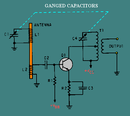
A typical RF amplifier is utilized in an AM radio receiver. In the schematic, the input circuit consists of the radio's antenna (L1, a coil), which is part of an LC circuit tuned to the desired station using a...

This class of amplifier is designed to follow low-level stages, such as a crystal oscillator. An oscillator requires an intermediate stage to prevent loading, ensuring that the input impedance is sufficiently high to avoid significant loading on the oscillator....

This circuit is capable of generating up to 1 W of audio power to drive a speaker or horn. When the CDS cell is exposed to light, its resistance decreases, activating NOR gate (a). This activation causes gates (a)...
Warning: include(partials/cookie-banner.php): Failed to open stream: Permission denied in /var/www/html/nextgr/view-circuit.php on line 713
Warning: include(): Failed opening 'partials/cookie-banner.php' for inclusion (include_path='.:/usr/share/php') in /var/www/html/nextgr/view-circuit.php on line 713