
Astable multivibrator using op amp negative feedback circuits
R1: The value of this resistor significantly affects the output pulse time period. Decreasing this resistance increases the time period, while increasing it decreases the time period.
R2: The pulse time period is directly dependent on this resistance value; increasing it results in a longer time period, whereas decreasing it shortens the time period.
R3: This resistor controls the brightness of the LEDs. Lowering this resistance increases brightness, while raising it decreases brightness. Values above 220 ohms are safe for use with the LEDs.
C1: The output pulse time period is directly proportional to this capacitance value. Increasing the capacitance value extends the time period, while decreasing it shortens the time period.
RV1: The output pulse time period is also directly proportional to the resistance introduced by this variable resistor. Increasing the resistance lengthens the output time period, while decreasing it shortens the time period.
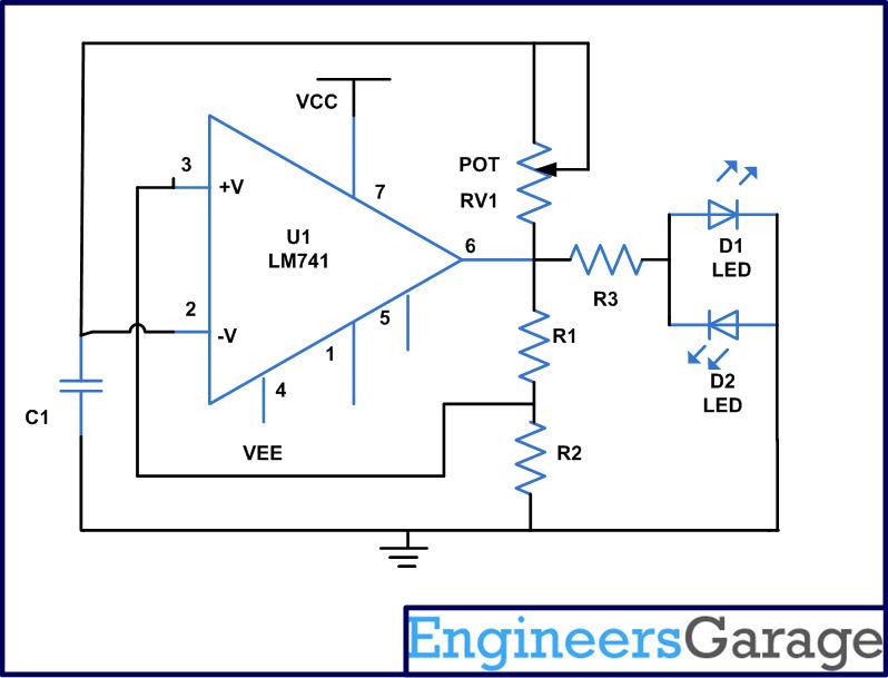
The astable multivibrator circuit using the 741 op-amp is a versatile and widely used configuration for generating square wave signals. The oscillation frequency and duty cycle can be adjusted by varying the resistor and capacitor values, making it suitable for applications such as timing circuits, pulse-width modulation, and LED flashing. The simplicity of the design allows for easy implementation, while the use of basic components, including resistors, capacitors, and an op-amp, contributes to its cost-effectiveness. Proper selection of component values is crucial for achieving desired output characteristics, allowing for fine-tuning of the pulse frequency and amplitude, which can be critical in various electronic applications. The circuit's feedback mechanism ensures stable oscillation, while the visual indication through LEDs provides immediate feedback on the circuit's operation.Astable multivibrator is an electronic device which can continuously shift between its two states with respect to the output. If the output corresponding to one particular state is high, then the output corresponding to the other state is low.
This nature of the circuit is useful in producing continuous output stream of pulses. There is no need fo r external triggering in case of astable multivibrator circuits. Simply turn on the power and the circuit start oscillating between its two states. Since it is an oscillator, a positive feedback can be found in this kind of circuits also. It is very easy to realize an astable multivibrator using op-amp ICs. The following circuit is an implementation of astable multivibrator using the 741 op-amp IC. In the above circuit, you can see a positive feedback introduced into the non-inverting pin of the 741 IC, after dividing the output voltage from pin6 using two resistors R1 and R2. There is a capacitor connected to the inverting pin of the op-amp. This capacitor charges through the pot RV1. Initially the capacitor is uncharged condition, and we can expect 0V at the inverting pin of the op-amp.
In this condition the output is high, and the non-inverting pin of the op-amp is getting a voltage, which is the output voltage divided by the two resistors. The capacitor starts charging to the high voltage of the output pin through the variable resistor RV1.
While it is charging the potential at the inverting pin gradually increases. Eventually at some point of time, the voltage at the inverting pin reaches slightly above the voltage at the non-inverting pin. At this point of time the output of the op-amp goes low (negative) abruptly. When the output pin becomes negative, the capacitor suddenly discharges to zero and then starts charging in the negative direction.
While it charges in the negative direction, the output remains low since the non-inverting pin is getting a low voltage divided from the output pin. At some point of time the voltage at the inverting pin reaches below the voltage of the non-inverting pin and the output goes high (positive) abruptly.
Now the capacitor again discharges to zero and start doing the same procedure again. Thus we get a continuous pulse train at the output, and are indicated by the two LEDs. R1: The value of this resistor has significant effect in the time period of the output pulse. If you decrease this resistance, the output pulse`s time period increases and if you increase this resistance, the output pulse`s time period decreases. R2: The pulse time period is directly depends on the value of this resistance. If you increase the resistance, the time period increases and if you decrease the resistance, the time period decreases.
R3: This resistance controls the brightness of the LEDs. Decreasing this resistance increases the brightness, and increasing this resistance decreases the brightness. The values above 220 ohms are safe to use with the LEDs. C1: The output pulse time period keeps a direct proportionality with the value of this capacitance. If you increase the value, the time period increases and if you decrease the value the time period decreases.
RV1: The output pulse time period also has a direct proportionality with the value the resistance introduced by this variable resistance into the circuit. If you increase the resistance, the output time period increases and if you decrease the resistance, the output time period decreases.
🔗 External reference
Related Circuits
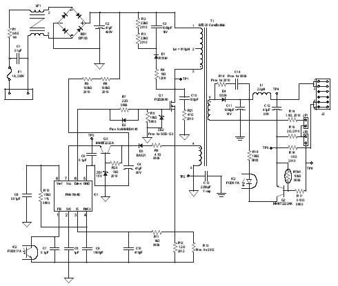
A high brightness LED evaluation board has been developed using the Fairchild Semiconductor FAN7554D PWM controller. The evaluation board for high brightness LEDs incorporates the Fairchild Semiconductor FAN7554D PWM controller, which is designed to provide efficient power management and precise...
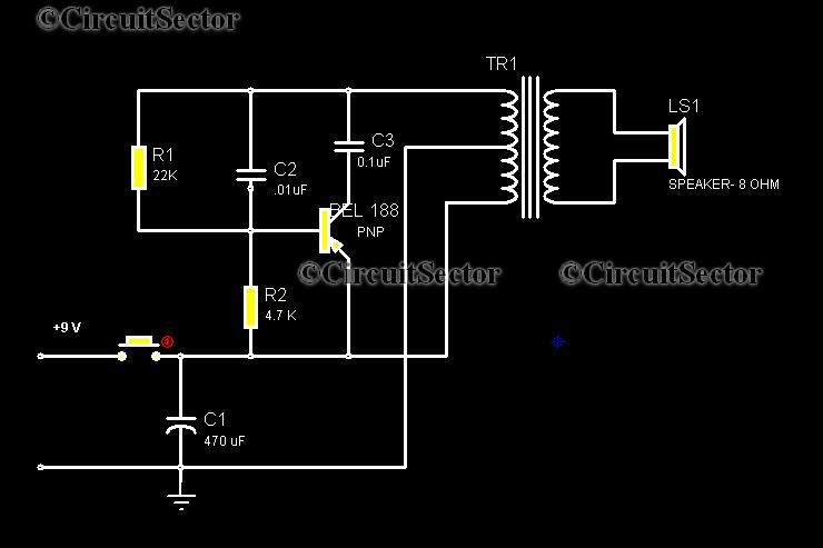
This circuit is a low-cost, one-touch doorbell using a Bel 188 transistor. It is likely one of the most economical bell circuits that can be constructed. The core component of this circuit is the output transformer from a push-pull...
This article explains the principle of the Audison LR604XR amplifier. The principle is straightforward; it is recommended to combine the text with a careful reading of the complete schematic. To fully understand this principle, it is advisable to review...
This guide provides instructions for installing an EDM/UKDM Honda Integra DC2 rear fog light on a 2005-2006 Acura RSX. The installation of an EDM/UKDM Honda Integra DC2 rear fog light on a 2005-2006 Acura RSX involves several key steps to...
A compact power amplifier that delivers high-quality sound. It incorporates a NE5534 operational amplifier, known for its excellent performance, capable of handling low loads, providing high speed, and exhibiting low distortion. Additionally, it features two V-MOSFET transistors at the...
This circuit is designed for use with inductive pick-up elements and dynamic microphones. Most soundcards feature a line input and a dedicated input for electret (condenser) microphones. To connect an inductive tape recorder head or a dynamic microphone, an...