
Preamplifier For Soundcard
This preamplifier circuit is designed to enhance the performance of inductive pick-up elements and dynamic microphones by providing necessary amplification and impedance matching, thus ensuring compatibility with various soundcard inputs. The use of discrete components allows for a customizable design that can be adapted to specific requirements while maintaining signal integrity. The careful selection of capacitors and resistors ensures that the circuit maintains a linear frequency response, which is crucial for applications requiring accurate sound reproduction. Additionally, the inclusion of feedback mechanisms enhances the stability of the circuit, preventing unwanted oscillations and ensuring reliable operation. The compact design facilitates easy integration into various audio systems, making it a versatile solution for audio engineers and hobbyists alike. Proper shielding and use of screened cables further protect the circuit from external noise, enhancing the quality of the audio signal processed through the soundcard.This circuit can be used for inductive pick-up elements and dynamic microphones Most soundcards have a line` input and one for an electret (condenser) microphone. To be able to connect an inductive tape-recorder head or a dynamic microphone, an add-on preamplifier is needed.
Even in this day and age of integrated microelectronics, a transistorised circuit built from discrete part has a right of existence. The preamplifier described in this short article goes to show that it will be some time before discrete transistors are part of the silicon heritage. The preamplifier is suitable for use with a soundcard or the microphone input of a modem. As you will probably know, most sound-cards have input sockets for signals at line level (stereo), as well as one for a (mono) electret microphone.
For the applications we have in mind, connecting-up an inductive pick-up element or a dynamic microphone, both inputs are in principle suitable, provided the source signal is amplified as required. The author eventually chose the microphone input on the soundcard. Firstly, because the line inputs are usually occupied, and secondly, because the bias voltage supplied by the micro-phone input eliminates a separate power supply for the preamplifier.
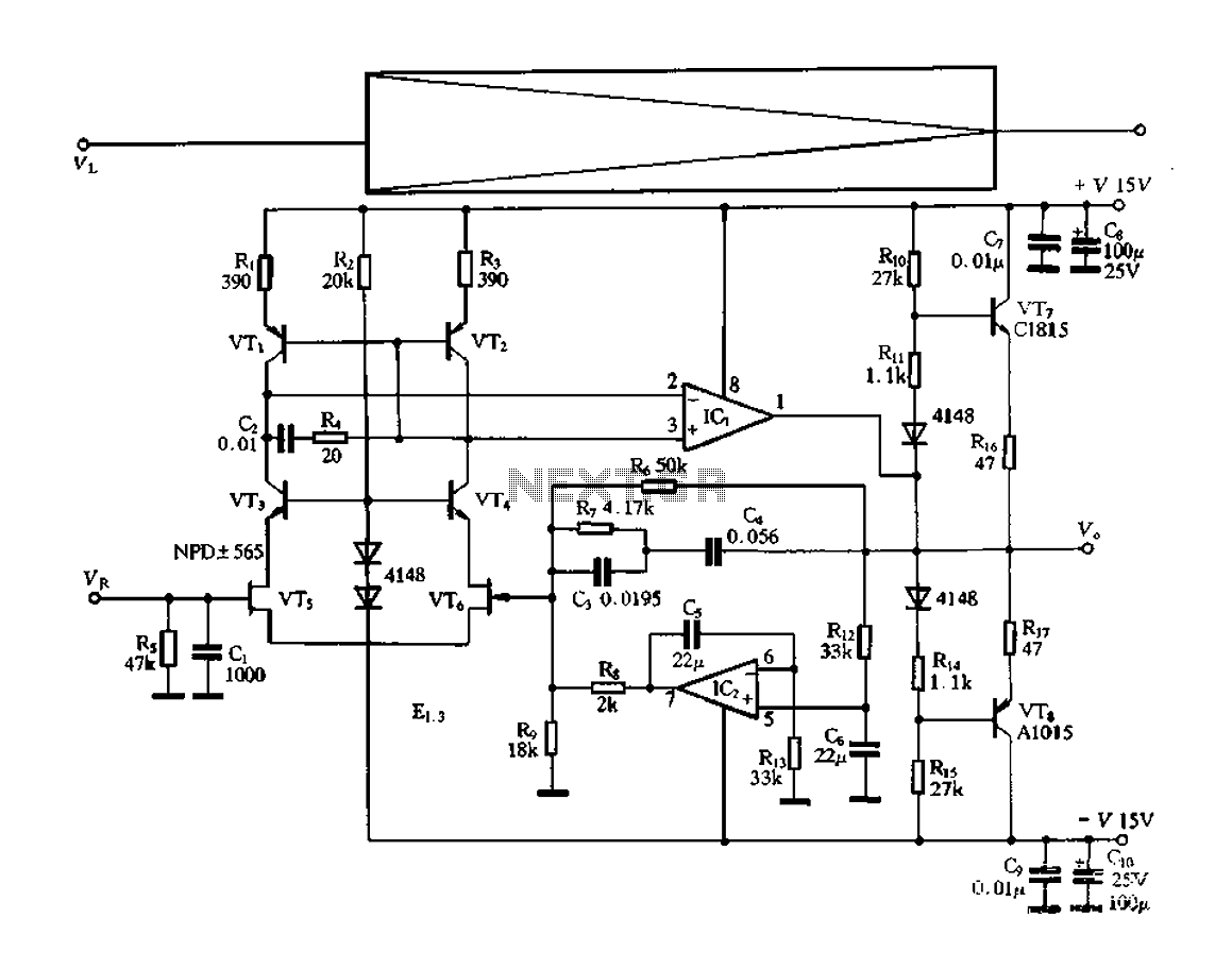
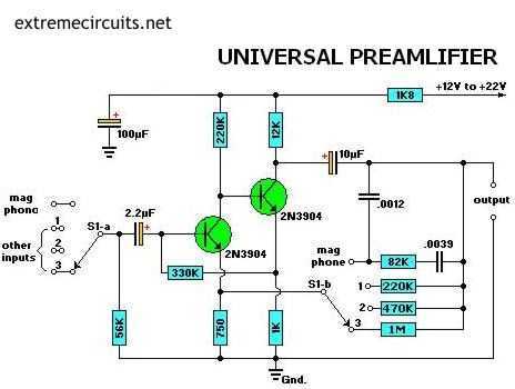
The microphone input of a soundcard will typically consist of a 3. 5-mm jack socket in stereo version, although only one channel is available. The free contact is used by the soundcard to supply a bias voltage to the mono electret microphone. This voltage is accepted with thanks by the present preamplifier, and conveniently obviates an external (mains adaptor) power supply. In true transistor-design fashion, the preamplifier consists of three stages. Capacitor C1 decouples the signal received from the microphone or pick-up element, and feeds it to the input of the first stage, a transistor in emitter configuration, biased to provide a current amplification of about 300 times.
Together with the source impedance of the microphone or pick-up element, capacitors C2 and C3 form a low-pass filter which lightly reduces the bandwidth. In addition, the output low-pass, R2-C3, reduces the dynamic collector resistance at higher frequencies.
In this way, the filter reduces the gain in the higher part of the frequency spectrum and so helps to eliminate any oscillation tendencies. The first, high-gain, stage is terminated by T2. Unlike T1, this transistor does not add to the overall gain, because the output signal is taken from the emitter (common-collector circuit).
T2 thus acts as an impedance converter, with C4 reducing any tendency to oscillation. The output stage around T3 is a common-emitter circuit again. In it, preset P1 determines the voltage amplification. T3 is biased by means of a direct-current feedback circuit based on components R7 and C5. To this is added an overruling` dc feedback path back to the input transistor, via R6. This measure guarantees good dc stability in the preamplifier. The circuit is small enough to be built on a piece of veroboard or stripboard, and yet remain reasonably compact. To prevent interference from external sources, the completed board should be mounted in a properly screened (metal) enclosure, with the connections to the input source and the sound card made in screened cable.
The preamplifier provides a frequency-linear response. In case the source signal is marked by frequency correction (e. g. , RIAA), then a matching linearization circuit should be used if the relevant signals are used by the computer. 🔗 External reference
Related Circuits
The electronic switch functions as a multifunctional preamplifier. It features a five-way touch electronic switch, a high-speed DC servo RIAA ultralow distortion amplifier, and can control volume, tone, and power amplifier electrical path phase. The TC9152, shown in Figure...
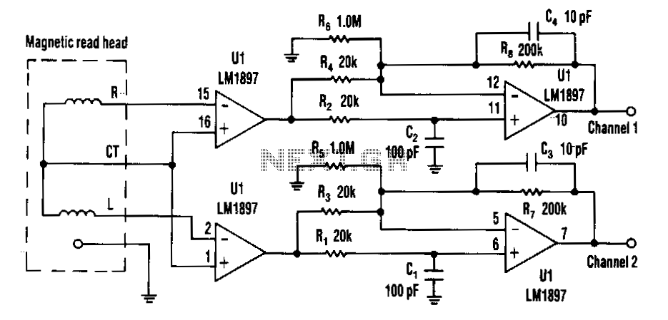
Choosing direct current (DC) coupling instead of alternating current (AC) coupling can significantly reduce the noise associated with preamplifiers for a magnetic reading head, particularly at low frequencies. The LM1897 eliminates the need for the capacitor that typically AC...
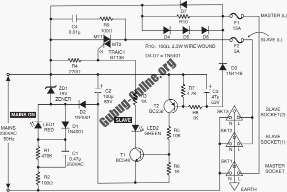
This circuit design features a modular arrangement that enables users to select only the modules best suited to their needs, allowing for the construction of a chain ranging from one to five modules in length. For those seeking a...
The amplifier drives a pair of loudspeakers using two LM3876 integrated power amp ICs (50 watts per channel), or a pair of headphones via a Meier crossfeed filter and an OPA2134 dual opamp. It provides four switchable line level...
The circuit was designed according to the RIAA implementation of a Hi-Fi phono preamplifier for the purpose of reproducing audio from a moving magnet cartridge. The RIAA (Recording Industry Association of America) equalization curve is essential for the accurate playback...
Most audio amplifier systems must have preamplifiers with many different characteristics. These include high-gain linear response for magnetic microphones, low-gain linear response for tuners, and high-gain RIAA equalization for magnetic phone cartridges. To meet this broad requirement, most amplifier...