
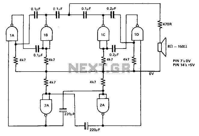
Audible ttl probe
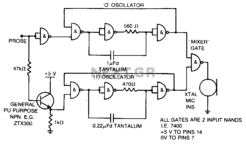
The described circuit operates as a simple audio output device that responds to digital logic levels. It utilizes a probe mechanism to detect TTL (Transistor-Transistor Logic) signals. The probe's function is to provide auditory feedback based on the logic state detected at its tip.
The circuit comprises a small audio oscillator, which generates sound frequencies corresponding to the logic levels. When the probe touches a point in the circuit that outputs a TTL low (0), the audio oscillator produces a low-frequency tone. This is typically achieved using a simple transistor-based oscillator or a dedicated audio IC configured to generate low frequencies. The frequency of the sound produced is determined by the components used in the oscillator circuit, such as resistors and capacitors.
In the case of a TTL high (1) signal, the circuit responds by generating a high-frequency tone. This can be accomplished by switching the oscillator's configuration or using a different oscillator circuit that is designed to produce higher frequencies. The transition between low and high tones provides a clear auditory indication of the detected signal state.
Powering the circuit from the circuit under test allows for portability and ease of use, as it eliminates the need for an external power source. The circuit must be designed to handle the voltage levels present in the circuit under test, typically ranging from 0 to 5 volts for TTL logic levels. Proper isolation and protection mechanisms should be implemented to prevent damage to the probe or the circuit under test.
Overall, this circuit serves as a practical tool for troubleshooting and testing digital circuits, providing immediate feedback through sound to indicate the state of the logic levels being probed.When the probe is in contact with a TTL low (0) the probe emits a low note. With a TTL high (1), a high note is emitted Power is supplied by the circuit under test. 🔗 External reference
Related Circuits
The current tracer is designed to identify a defective integrated circuit (IC) that is causing excessive loading on the power supply. It amplifies the small voltage drop that occurs due to current flow over a short length of printed...
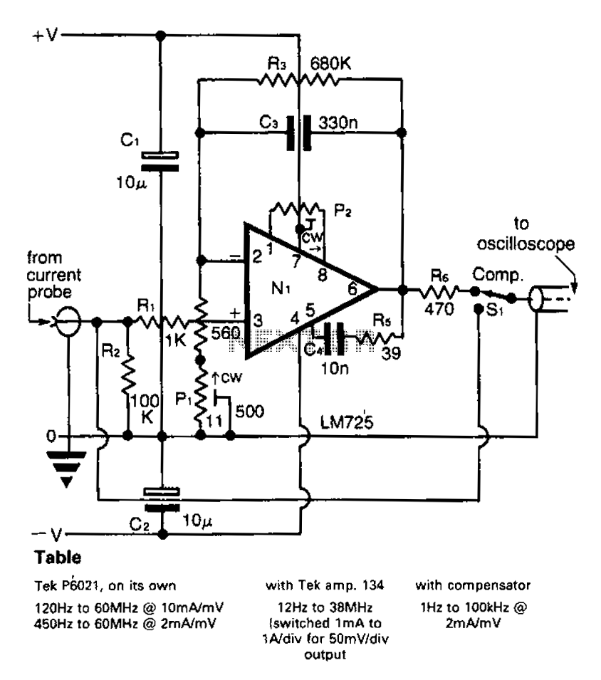
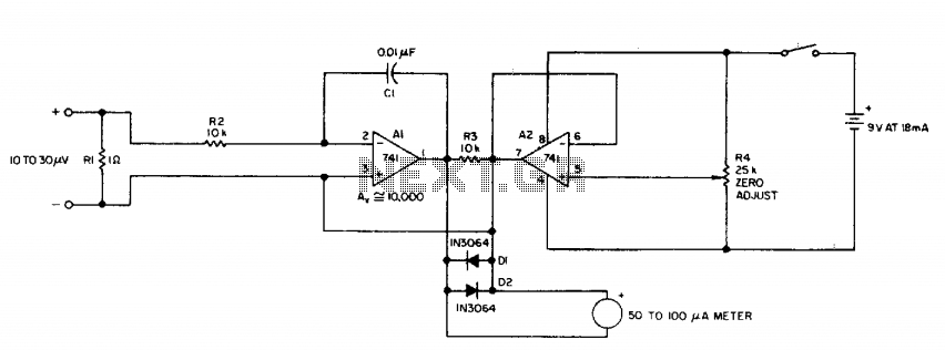
A clip-on current probe, like the Tektronix P6021, is a valuable tool for displaying current waveforms on an oscilloscope. However, it has limitations in low-frequency response. Specifically, the P6021 is sensitive to a range of 2mA/mV, and frequencies below...
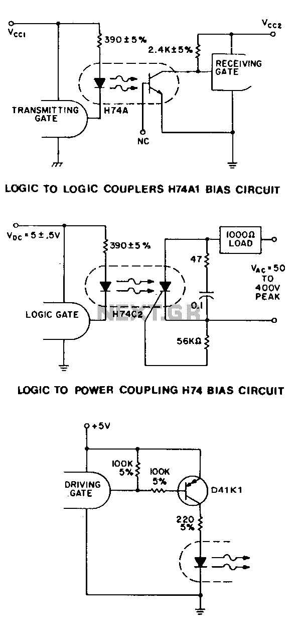
For higher speed applications, up to 1-MHz NRZ, the Schmitt-trigger output HllL series optoisolator provides many features. The 1.6-mA drive current allows fan-in circuitry to drive the IRED, while the 5-V, 270-0 sink capability and 100ns transition times of...
The siren comprises two oscillators that generate tones. A third oscillator is utilized to alternately switch the others on and off, creating a two-tone effect. By adjusting the capacitor values, different tones can be produced. The siren circuit is designed...
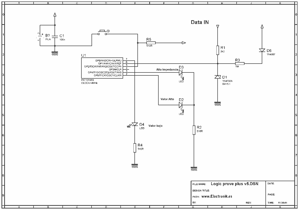
This project is based on a probe logic states, capable of measuring levels from TTL (5v) to state levels of PLC's (24v). For this we have employed the use of the PIC 12F683 microcontroller, which by its nature is...
This free-running TTL square-wave oscillator features a variable frequency output spanning a 20:1 range or better. It utilizes four of the six inverters in an SN7404 chip along with additional components. The frequency of oscillation is dictated by the...