
Siren uses TTL gates
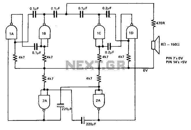
The siren circuit is designed to produce a distinctive sound through the interaction of multiple oscillators. The primary components include two tone-generating oscillators, typically configured as astable multivibrators or similar oscillator circuits, which operate at different frequencies. The output of these oscillators is fed into a speaker or a piezoelectric transducer to create audible sound.
The third oscillator serves a crucial role in modulating the output of the first two. This oscillator can be configured as a simple square wave generator, which toggles the activation of the two tone generators. By controlling the duty cycle and frequency of this third oscillator, the timing of the on and off states of the first two oscillators can be finely adjusted, allowing for a variety of two-tone patterns.
Capacitor values in the circuit are significant because they influence the timing characteristics of the oscillators. By selecting different capacitor values, the frequency of oscillation can be altered, resulting in different tonal outputs. This allows for customization of the siren's sound, making it adaptable for various applications, such as alarms, alerts, or signaling devices.
In designing the circuit, it is essential to ensure that the power supply is stable and capable of providing the necessary current for the oscillators and the output device. Additionally, proper filtering may be required to minimize noise and ensure clear tone generation. The implementation of resistors in conjunction with the capacitors will also affect the rise and fall times of the oscillators, further shaping the sound produced by the siren.
Overall, the siren circuit's versatility and simplicity make it an effective tool for generating attention-grabbing alert signals in numerous electronic applications.The siren consists of two oscillators which generate the tones. A third oscillator is used to switch the others on and off alternately, giving the two-tone effect. By changing the capacitor values different tones can be produced. 🔗 External reference
Related Circuits
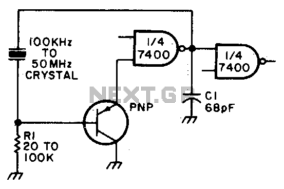
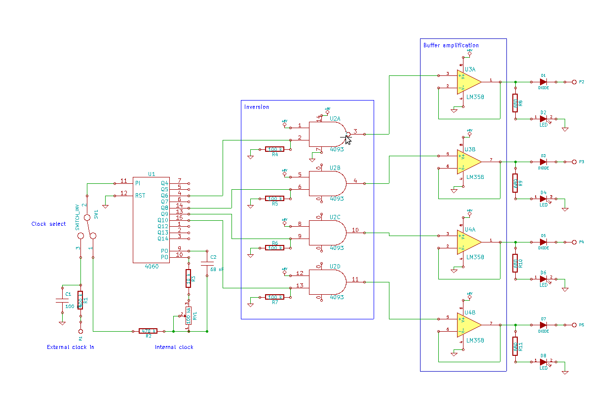
Adjust Rl for approximately 2 volts at the output of the first gate. Additionally, adjust Cl for optimal output. In the context of electronic circuit design, the output voltage of a gate, such as a logic gate or operational amplifier,...
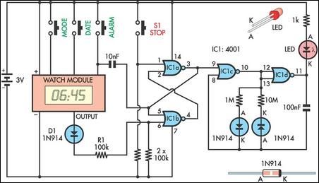
This device serves as a daily medication reminder. It incorporates a crystal watch and a 4001 quad 2-input NOR gate, with two of the gates (IC1a and IC1b) configured as an RS flip-flop. The watch is programmed to signal...
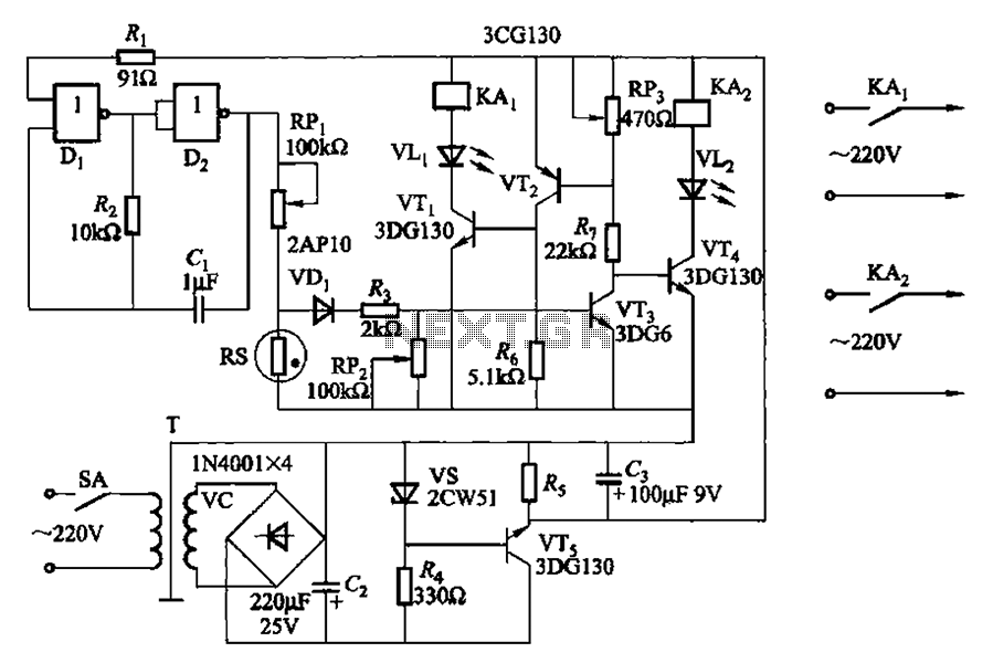
Two NAND gates (Di, Dz) and a resistor (Rz) along with capacitors (C1, etc.) form an RC self-excited multivibrator with an oscillation frequency of 2.5 Hz and an oscillation amplitude of 4 V. This circuit is used as a...

A loud sweeping siren-type audio sound generator powered by 3V. The circuit utilizes an LTC1799 precision frequency generator from Linear Technology and a 74HC14 hex Schmitt trigger from Texas Instruments to perform various functions. One section is configured as...
This blog showcases project documentation of various projects completed by members of the Association of Experimental Electronics. Some projects are beginner-friendly, while others are intended for more advanced solderers. The core components of this sequencer were assembled during the...

This is a simple siren sound generator with high power output and significant noise levels. The circuit utilizes digital integrated circuits (ICs), specifically the CD4046, in an inverter configuration along with four transistors to increase the current output to...