
Audio Analogue Level Meter
This audio level monitoring circuit utilizes a small panel meter to provide visual feedback of audio signal levels. The design incorporates discrete components and is structured around two common emitter amplifier stages, which are essential for achieving the desired gain and frequency response characteristics. The circuit is capable of operating effectively within the audio frequency range, specifically from 20 Hz to over 50 kHz, ensuring that it can accurately monitor a wide variety of audio signals.
The input sensitivity of the circuit is set at 100 mV, which corresponds to a full-scale deflection on a 100 µA meter. This sensitivity allows for the detection of low-level audio signals, making it suitable for various applications in audio engineering and testing. The first amplifier stage features a preset resistor that can be adjusted to calibrate the full-scale deflection (FSD) of the meter, providing flexibility in accommodating different input signal levels.
The last stage of the circuit is designed to be biased at approximately half the supply voltage. This biasing technique maximizes the AC voltage swing, ensuring that the output can accurately reflect the variations in the audio signal. The audio frequencies are coupled into the circuit through a 10 µF DC blocking capacitor, which prevents any DC offset from affecting the measurement.
To convert the AC audio signal into a varying DC voltage suitable for the meter, a full-wave bridge rectifier is employed. This rectification process allows for the measurement of both the positive and negative halves of the audio waveform, providing a more accurate representation of the audio levels. The output from the rectifier is a varying DC voltage that corresponds to the amplitude of the incoming audio signal, which can then be displayed on the panel meter.
Overall, this circuit design is an effective solution for monitoring audio levels, combining simplicity with functionality to provide reliable performance in various audio applications.Audio levels can be monitored using a small panel meter with this circuit built from discrete components. The circuit has a flat frequency response from about 20Hz to well over 50Khz. Input sensitivity is 100mV for a full scale deflection on a 100uA meter. Built on two common emitter amplifiers, the first stage has a preset resistor which may be adjusted for a FSD.
The last stage is biased to operate at roughly half the supply voltage for maximum ac voltage swing. Audio frequencies are passed through the 10u dc blocking capacitor and the full wave bridge rectifier converts the signal to a varying dc voltage. Note th 🔗 External reference
Related Circuits
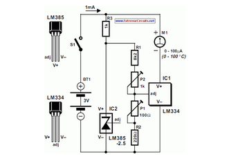
The circuit of the Celsius thermometer in the diagram is based on the well-known Type LM334 from National Semiconductor. This integrated circuit (IC) serves as a sensor that provides temperature readings. The Celsius thermometer circuit utilizes the LM334 integrated circuit,...
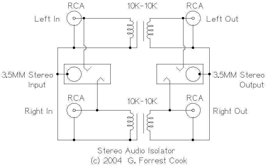
This circuit is useful for removing ground loop hum on a remote line level audio signal line. It can be used to connect a computer sound card to a stereo amplifier's line input. Other uses include tapping into a...
The operation is completely safe due to protection against DC and AC short circuits between all pins and ground, thermal over-range conditions, load dump voltage surges up to 40V, and accidental open ground situations. The circuit design incorporates multiple safety...
The tool is based on a NE555 (or LM555) timer i.c., wired as an astable multivibrator. The frequency of the multivibrator is determined by the value of the unknown capacitor Cx. The circuit can be fed by a small...
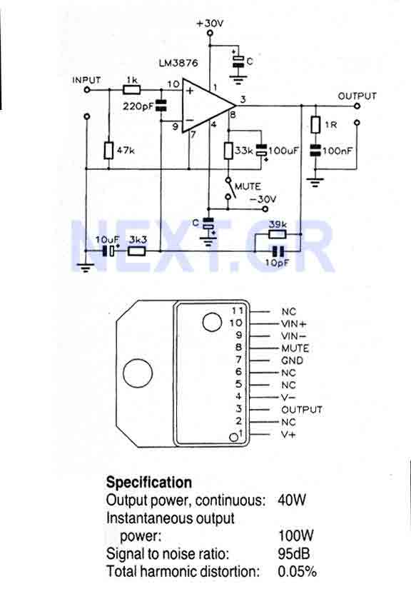
This Circuit is based on the LM3876. A 11-pin plastic package IC with high performance audio power amplifier, an output mute function which can be used to eliminate switch-on and switch-off "thumps" to the loudspeaker load. It is capable...
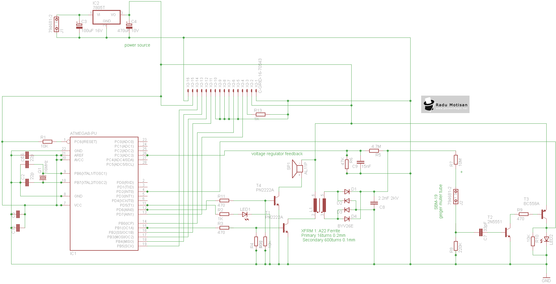
An efficient and stable construction for radiation dosimetry needs. The design centers around the Atmel Atmega8 microcontroller and a Russian Geiger Muller tube, specifically the CTC-1 tube for high gamma doses. The dosimeter is compatible with various tubes including...