
Capacitance meter with 555

More: The cycle length of the square wave which is produced by the NE555 can be determined using the following formula:
T = 0.7 * Cx * (R1 + 2 * R2)
[Cx in Farad, R in Ohms, R1 is the resistor between pins 7 and 8 and R2 the resistor between pins 7 and 6 of the i.c.]
When R1 = 1000 Ohms and R2 = 215 Ohms, a capacitor of 1 uF will produce a 1 ms cycle. If you measure large electrolytics (1000 uF or more), you must wait several seconds before you get any display reading on the frequency counter. With this combination of R1 and R2, you can measure capacitors between about 0.1 uF and 5000 uF. Smaller capacitors can be tested if R1 and R2 are made larger (e.g., using 1M and 215k, an 1 nF capacitor will produce a cycle length of 1 ms). However, when small capacitors are measured the capacitance of the wiring must be taken into account (e.g. a capacitor of 1000 pF may give a reading of 1050 pF if the wiring has a capacitance of 50 pF). When Cx is greater than 1 uF, stray capacitance can be neglected. For an accurate reading, R1 and R2 should be 1% metal oxide resistors.
The described circuit utilizes a NE555 timer integrated circuit configured as an astable multivibrator, which is capable of generating a square wave signal whose frequency is determined by external resistors (R1 and R2) and a capacitor (Cx). The NE555 timer is a versatile device commonly used in various timing applications due to its reliability and ease of use.
In the astable configuration, the timer continuously oscillates between its high and low states, producing a square wave output. The frequency (f) and the cycle length (T) of this output can be calculated using the aforementioned formula. The values of R1 and R2 play a crucial role in establishing the timing intervals, while Cx varies the capacitance to adjust the frequency output.
The circuit is powered by a 9V battery connected to the appropriate pins of the NE555. The use of an on/off switch allows for convenient control of the circuit's operation. The output from the NE555 is fed into a digital frequency counter, which is configured to measure the cycle length of the square wave rather than the frequency. This is particularly useful for applications requiring precise timing measurements, such as in capacitor testing.
The choice of R1 and R2 values directly impacts the range of capacitance that can be measured. By selecting higher resistor values, smaller capacitors can be tested effectively, although the effects of stray capacitance in the wiring must be considered for accurate readings. The use of 1% tolerance metal oxide resistors is recommended for improved measurement accuracy, ensuring that the resistive components do not introduce significant error into the timing calculations.
Overall, this circuit serves as a functional tool for measuring capacitance across a wide range, making it an essential component for electronics enthusiasts and professionals alike.The tool is based on a NE555 (or LM555) timer i.c., wired as an astable multivibrator. The frequency of the multivibrator is determined by the value of the unknown capacitor Cx. The circuit can be fed by a small battery. I use myself a 9 V block battery which is connected to pins 4 and 8 of the i.c. via an on/off switch. The output of the multivibrator is connected to the digital frequency counter. The counter should assess the cycle length of the square wave, not the frequency (on most frequency counters, one can select either frequency measurement or measurement of the cycle length). A wave with a frequency of 1 kHz (i.e. 1000 Hz) has a cycle length of 1 millisecond. The cycle length of the square wave which is produced by the NE555 can be determined using the following formula: T = 0.7 * Cx * (R1 + 2 * R2) [Cx in Farad, R in Ohms, R1 is the resistor between pins 7 and 8 and R2 the resistor between pins 7 and 6 of the i.c.] When R1 = 1000 Ohms and R2 = 215 Ohms, a capacitor of 1 uF will produce a 1 ms cycle. If you measure large electrolytics (1000 uF or more), you must wait several seconds before you get any display reading on the frequency counter.
With this combination of R1 and R2, you can measure capacitors between about 0.1 uF and 5000 uF. Smaller capacitors can be tested if R1 and R2 are made larger (e.g., using 1M and 215k, an 1 nF capacitor will produce a cycle length of 1 ms). However, when small capacitors are measured the capacitance of the wiring must be taken into account (e.g.
a capacitor of 1000 pF may give a reading of 1050 pF if the wiring has a capacitance of 50 pF). When Cx is greater than 1 uF, stray capacitance can be neglected. For an accurate reading, R1 and R2 should be 1% metal oxide resistors. 🔗 External reference
Related Circuits

When the system is placed in a shop or mall, logos and product advertisements serve as an ideal complement to temperature information. For home use, photographs of children at the beach or, should the temperature drop, images of making...
This project involves a straightforward and practical moisture level LED meter circuit, which serves as a sensor or detector to measure humidity or moisture levels in various materials such as plants, soil, wood, walls, and floors. The moisture level LED...
This circuit can drive analog moving coil meters, for use as a VU meter. The circuit is left connected to the line terminals of the amplifier. The VU meter works pretty simple. T1 and T2 signal increase. The signal...

This circuit utilizes a simple calculator along with a chip-on-board (COB) from an analog quartz clock to create a telephone call meter. The calculator converts STD/ISD calls into local call equivalents and continuously displays the current local call meter...
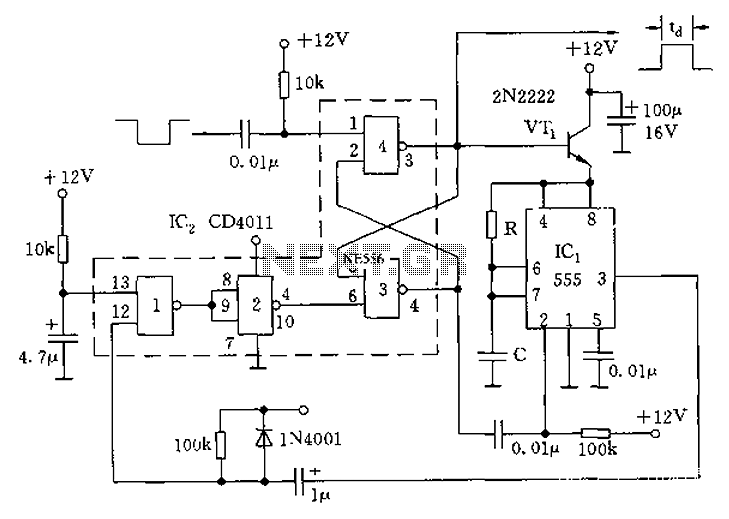
The circuit consists of four 2-input NAND gates and a CMOS CD4011 type 555 timer, allowing for either a static or high-time period output while maintaining minimal power consumption. Additionally, the circuit features a 3-door and 4-door composition RS...
Construction of a 1-Wire Barometer. This page shows the circuit and provides construction and calibration details. This barometer connects to a Dallas Semiconductor 1-Wire network. The 1-Wire Barometer is designed to measure atmospheric pressure and transmit this data over a...