
Audio Booster circuit
The described amplifier circuit is designed for a nominal gain of 20 dB, which is a common requirement in audio applications to ensure adequate signal amplification without distortion. The frequency response characteristics indicate that the circuit is well-suited for a wide range of audio frequencies, from the low bass to the high treble, with a specific focus on maintaining a flat response in the mid to high frequency range.
The critical components influencing the frequency response are C1 and R1. The capacitor C1 plays a pivotal role in defining the low-frequency roll-off characteristics of the amplifier. The fixed resistance of R1 provides a stable reference, but it is the capacitance value of C1 that dictates the behavior of the circuit at lower frequencies.
When C1 is set to 0.1 pF, the circuit's corner frequency is lowered to 70 Hz, which allows for better performance in reproducing lower frequencies. This adjustment is particularly beneficial in applications where bass response is crucial. If a further reduction in the corner frequency is desired, swapping C1 for a 1.0 pF capacitor can achieve an even greater low-end roll-off.
In the case of using an electrolytic capacitor for C1, it is vital to observe the correct polarity during installation. Connecting the capacitor in reverse can lead to failure or damage to the component and potentially affect the overall functionality of the amplifier. The positive terminal of the electrolytic capacitor must be connected to the base terminal of transistor Q1, ensuring that the circuit operates as intended.
Overall, this amplifier circuit is designed with specific attention to frequency response and component interaction, making it suitable for a variety of audio applications where both high fidelity and low-frequency performance are necessary.The amplifier`s gain is nominally 20 dB. Its frequency response is determined primarily by the value of just a few components-primarily C1 and R1. The values of the schematic diagram provide a response of ±3. 0 dB from about 120 Hz to better than 20, 000 Hz. Actually, the frequency response is ruler flat from about 170 Hz to well over 20, 000 Hz; it` s the low end that deviates from a flat frequency response. The low end`s roll-off is primarily a function of capacitor C1(since RI`s resistive value is fixed). If C1`s value is changed to 0. 1 pF, the low end`s comer frequency-the frequency at which the low-end roll-off starts-is reduced to about 70 Hz. If you need an even deeper low-end roll-off, change C1 to a 1. 0 pF capacitor; if it`s an electrolytic type, make certain that it`s installed into the circuit with the correct polarity, with the positive terminal connected to Q1`s base terminal.
🔗 External reference
Related Circuits
The circuit depicted in the figure is designed for multi-temperature testing, allowing for the switching of the thermocouple corresponding to the active channel. At the core of this design is a 555 timer configured in a monostable delay mode....
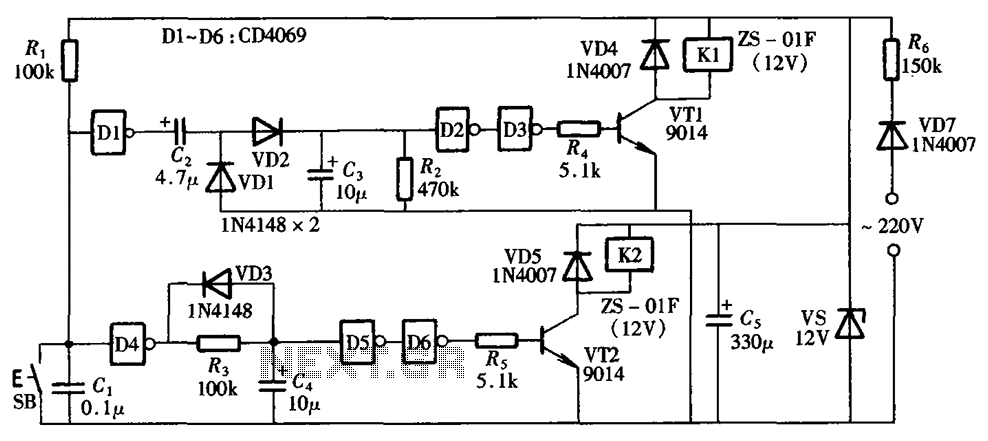
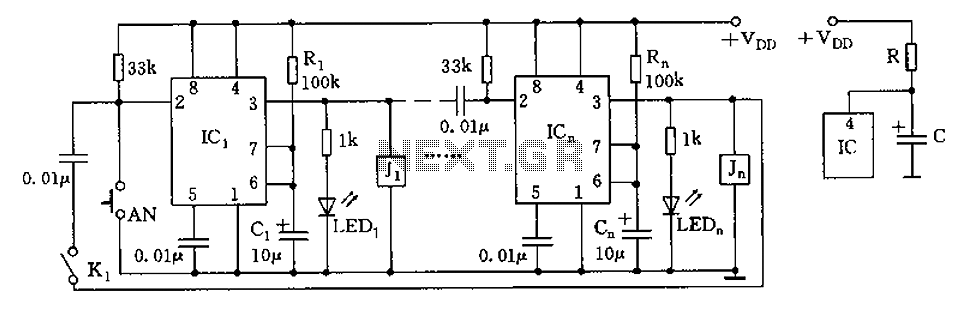
A one-button control switch is designed to control two relays, each of which can switch the load power on and off as needed. The circuit primarily consists of a hex inverter CD4049 and two self-locking DC relays. The circuit utilizes...
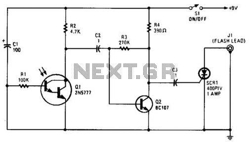
The phototransistor Q1 receives a light pulse from a photoflash unit. The pulse is AC-coupled to amplifier Q2, which subsequently triggers SCR1, activating a flash unit connected to J1. The circuit begins with the phototransistor Q1, which is sensitive to...
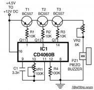
This is a simple home telephone ringtone generator circuit constructed using only a few electronic components. It generates a simulated telephone ringtone and requires a DC supply voltage ranging from 4.5V to 12V. This circuit can be used in...
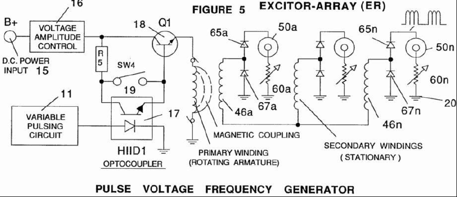
A power supply system utilizes a generator as a source of fuel to separate hydrogen and oxygen gases from natural water. It has the capability to control gas production by varying the amplitude of the voltage and/or the pulse...
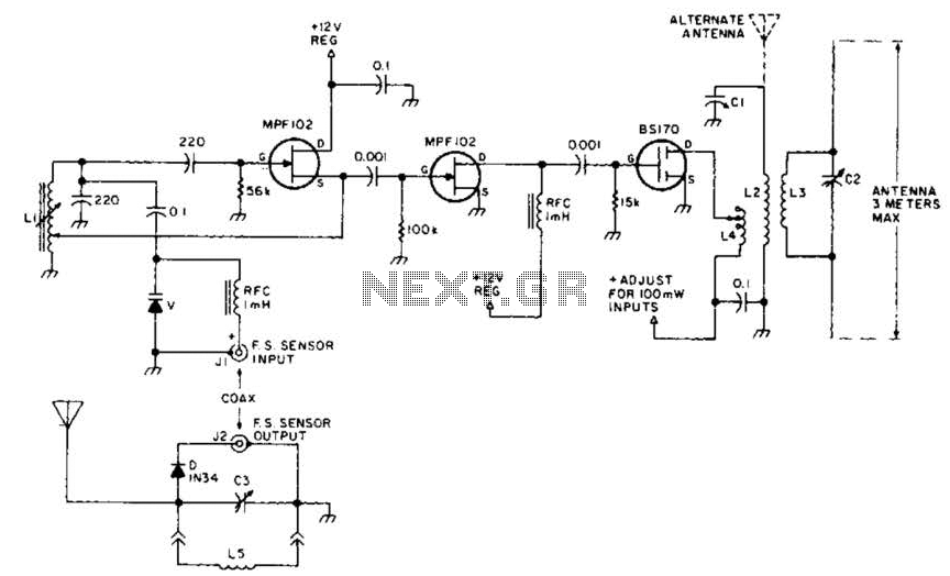
This field strength meter consists of a tuned crystal detector that generates a DC output voltage from a transmitted signal. The DC voltage is utilized to modulate the frequency of a transmitter with a power output of 100 mW,...