
555-channel temperature test circuits
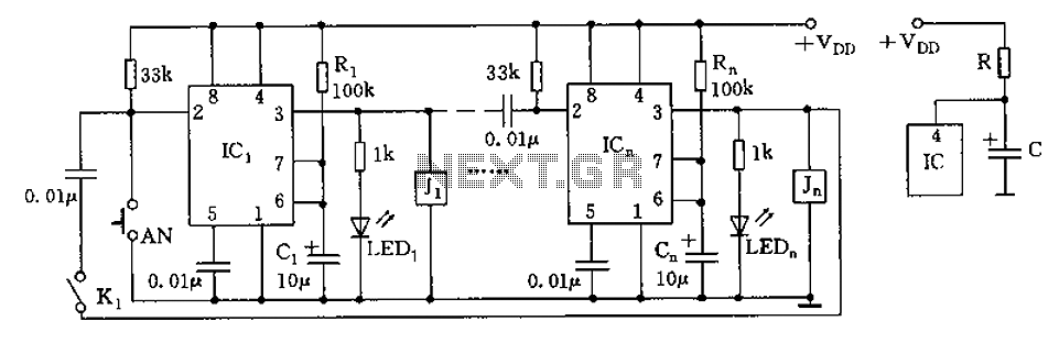
The circuit operates effectively by utilizing two 555 timer ICs configured in a monostable mode to manage the timing and switching of the thermocouple channels. The first timer (IC1) initiates the measurement process, while the second timer (IC2) ensures the thermocouple is activated for the duration of the measurement. The use of a capacitor (C1) and resistor (R1) not only defines the timing characteristics but also stabilizes the output by preventing sudden voltage changes that could lead to inaccurate readings. The configuration ensures that when the circuit is powered, the initial flickering of the LEDs indicates the system is operational, while the R-C network enhances the reliability of the reset mechanism, providing a more consistent and accurate measurement cycle. The design is particularly useful in applications requiring precise temperature monitoring across multiple channels, making it suitable for laboratory testing and industrial applications where temperature variations are critical. Circuit shown in Figure, when used in multi-temperature test, switch the thermocouple corresponding channel. 555 brightest are at the core monostable delay circuit, such as Cli ck AN, because the 2-pin was low, the IC1 set, was 3 feet high, J1 pull, the thermocouple channel ON. Meanwhile, C1 through R1 charging it, when the charging voltage reaches the threshold level 6 feet 2/3Vdd, the 555 reset pin 3 referred to the low level, in turn triggering a second stage IC2, the IC2 set, turns ON Road thermocouple, and then click the trigger.
If J1 is closed, the cycle can be monitored. Each level of the delay time (ie measuring time) td 1.1R1C1, icon parameter corresponding delay is about 1 second. LED1 ~ LEDn LEDs also turn lights, as a monitoring indicator. Figure a circuit when power-up, there are a few pieces of LED light tubes flicker at the same time, therefore, to improve the circuit shown in Figure b.
After accessing R, C network, boot, since C voltage can not change suddenly, so that the reset terminal pin 4 is forced reset state, 3 feet showed low output, as the charging capacitor C, so that was 4 feet high level, IC trigger timing in a wait state levels, have improved the accuracy of the test.
Related Circuits
This page outlines the development of electronics for displaying a monochrome video image on an electrostatic oscilloscope tube. This work complements the Electron Optics section in the Experiments category. The primary objective is to showcase a moving video image...
A collection of guitar fuzz, preamp, and operational amplifier (op-amp) electronic circuits and schematics designed for various guitar effects and distortion effects. This compilation includes a diverse range of electronic circuits that cater to guitarists seeking to enhance their sound...
This circuit controls a load, specifically a DC brushless fan, based on temperature compared to a setpoint. The transducer used is a diode operating in the forward polarization regime. When forward-biased, the forward voltage drop across the diode exhibits...
A low resistance (0.25 - 4 ohm) continuity tester for checking soldered joints and connections. This simple circuit uses a 741 op-amp in differential mode as a continuity tester. The voltage difference between the non-inverting and inverting inputs is...
This section includes intruder alarms for homes, cars, and motorcycles, as well as power failure alarms, water level alarms, and a snore detector. All circuits are organized alphabetically on the Circuit Index page and chronologically on the update page....
The decision to use electric power was made due to its quieter operation, lack of odor, and ease of carrying the bike up a flight of stairs. The selected conversion kit is manufactured by Currie. Although factory service is...