
Audio continuity tester
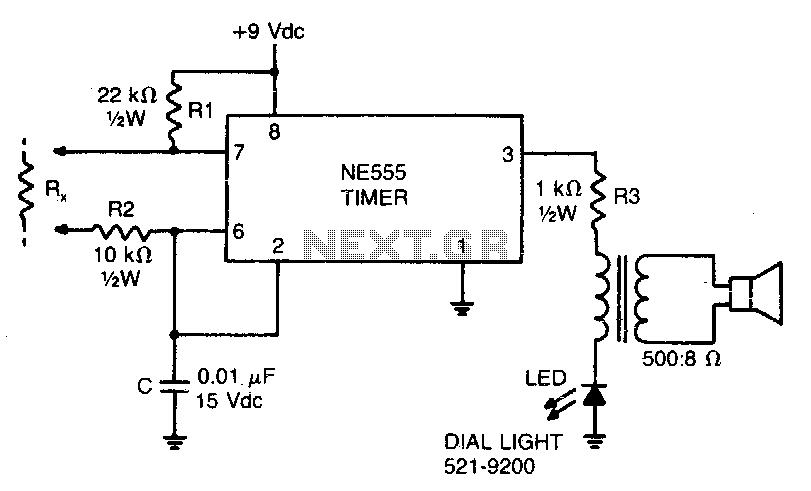
The low-current audio continuity tester is designed to provide a visual and auditory indication of resistance levels in electronic circuits. The principle of operation is based on generating an audio tone whose frequency varies in accordance with the resistance measured. This device typically employs a simple oscillator circuit that produces a continuous audio signal.
In practical applications, when the resistance is low, the audio frequency increases, resulting in a high-pitched tone. Conversely, as the resistance increases, the frequency of the audio tone decreases, producing a slower pulsing sound. This functionality allows users to quickly assess the integrity of components and connections within a circuit, making it an invaluable tool for troubleshooting and maintenance.
The tester can measure resistances up to 30 megohms, which is particularly useful for testing high-resistance components such as capacitors or insulators. The device is often powered by a low-voltage battery to ensure safety and minimize current draw during testing.
The schematic for such a continuity tester typically includes an oscillator circuit, often built around a transistor or an operational amplifier, connected to a speaker or a piezo buzzer for audio output. Additionally, a variable resistor may be included to calibrate the frequency response, ensuring accurate tone generation across the specified resistance range. Proper design considerations must be taken into account to ensure that the tester operates effectively without introducing significant loading effects on the circuit being tested.This low-current audio continuity tester indicates the unknown resistance value by the frequency of audio tone A high tone indicates a low resistance, and a tone of a few pulses per second indicates a resistance as high as 30 megohms. 🔗 External reference
Related Circuits
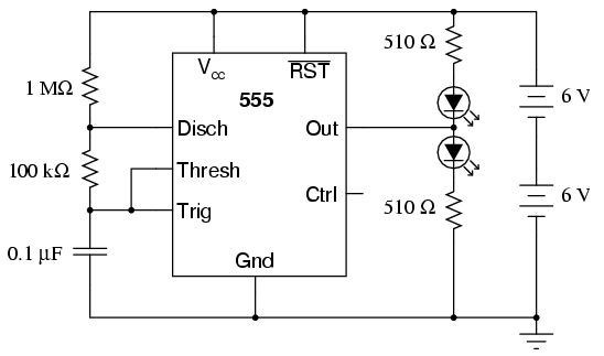
The 555 integrated circuit is a versatile timer that can be used for various applications. This experiment focuses on its operation as an astable multivibrator or oscillator. When connected to a capacitor and two resistors, it generates a square-wave...
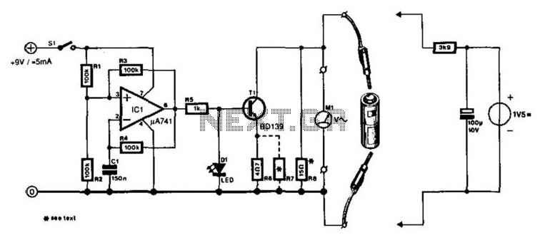
A designer often needs to know the internal resistance value of a battery. Many testers provide a relative indication of this value, but it is seldom expressed in ohms. The current tester can, in principle, provide this information. The...
Utilizing an analog audio line delay, it is possible to virtually adjust the size of a room. By simply turning a knob on the audio equipment, one can modify the perceived room size. The circuit described herein facilitates this...
What value of potentiometer should be used for the volume control of this audio amplifier circuit, and where should it be connected? Thank you. In audio amplifier circuits, the choice of potentiometer value for volume control is crucial for achieving...
The problem with class-B amplifier design is that we start with an output stage in two halves, each with a non-linear response, which we then add together to try to give a linear response, i.e. so that a graph...
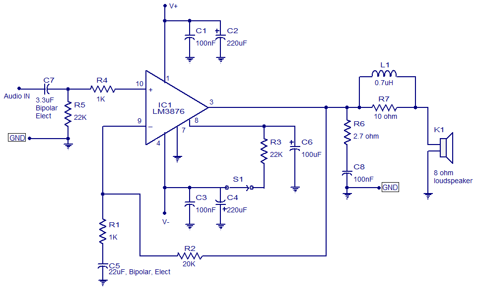
LM3876-based 50-watt audio amplifier circuit. Operates from +/-35V DC. Simple design, low noise. The LM3876 is a high-performance audio power amplifier designed for driving speakers in various audio applications. This particular circuit configuration enables the amplifier to deliver up to...