
Analog Audio Delay Line(3d Sound)
The circuit's architecture is designed to create a seamless audio experience that enhances the listener's perception of space. The SAD512D integrated circuit is pivotal, as it provides the necessary delay to simulate distance. The use of a fourth-order low-pass filter in the initial and final blocks ensures that high-frequency noise is attenuated, preserving the integrity of the audio signal while allowing for the desired delay. The adjustable delay feature allows for customization based on the specific acoustic characteristics of the environment.
The variable resistor R9 is crucial for maintaining audio fidelity, as it allows for precise control over the input signal's offset. This adjustment is essential to prevent distortion that could arise from excessive signal levels, thus ensuring a clear and pleasant listening experience. The cascading of two units to achieve a 30-meter virtual room effect demonstrates the circuit's scalability and versatility, making it suitable for various applications, from home theater systems to sound design in professional settings.
In summary, this circuit not only provides a practical solution for simulating larger acoustic spaces but also emphasizes the importance of careful tuning and adjustment to achieve optimal audio performance. The integration of advanced components, such as the SAD512D, alongside thoughtful circuit design, results in a sophisticated audio processing tool that can enhance the listener's experience significantly.Using analog audio line delay, you can adjust your room virtually. Just turn a knob in your audio set and you can adjust your room size. The circuit described here will make your dream come true, giving a feel that your speaker is located 15 meters behind you, even though your room is actually 3 meters wide. Here is the circuit`s schematic diagram. The core of this circuit is SAD512D integrated circuit, an analog audio delay. The chip uses 512 capacitors memory to hold 512 sampled analog signal. The delay can be adjusted from about 5, 1 ms to 51 ms by R12 pot. Feed the input of this analog delay circuit with a mixed right and left audio signals from your stereo system. The output of this circuit then fed to a small power amplifier and place the output speaker behind you.
Now you can perceive like your speaker is 15 m away behind (with maximum delay setting). If you build two unit the cascading the circuit will result in 30 meter expansion of your virtual room. The circuit consist three main block. The first block (U1A, U1B) is a fourth order low pass filter (-24dB roll-off per octave) with 2. 5kHz cut off frequency. The second block is the adjustable analog delay integrated circuit (IC SAD512D). The delay is controlled by the oscillator around U2 which is adjustable from 5KHz to 50Khz. The last block is similar to the first block, a low-pass filter with 2. 5KHz cut off frequency. A variable resistor R9 is provided to adjust the input offset, avoiding signal clipping and maximizing the audio range.
For easy adjustment, feed the input with high level audio signal until the output is distorted, then adjust R9 until the distortion is minimum, or if an oscilloscope is available, adjust the R9 until the clipping is equal for both positive and negative cycle. Finally, adjust R28 to give minimum sampling clock noise. 🔗 External reference
Related Circuits
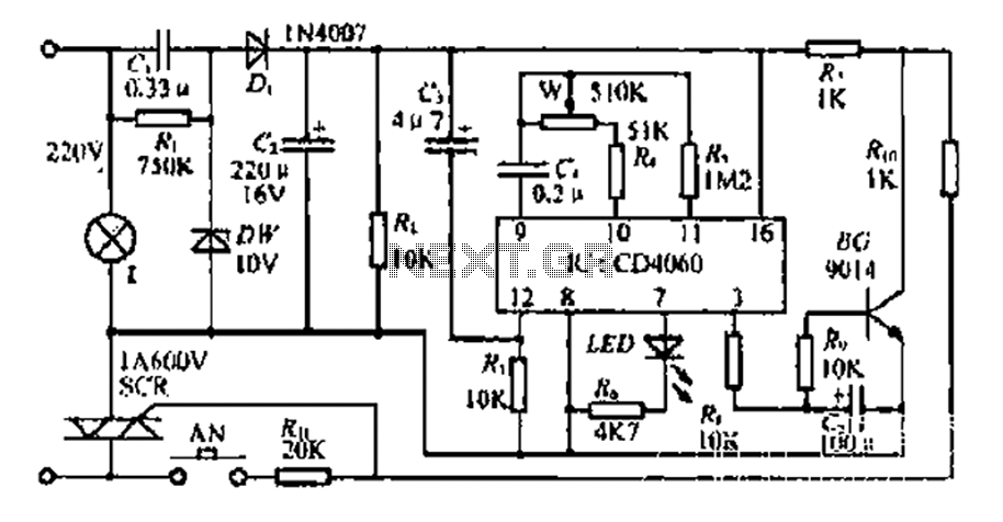
The circuit includes a CD4 component with a connection of 16 feet for the Vcc terminal, 8 feet for the ground, 12 feet for the reset terminal, 7 feet for the Qt end, and 3 feet for the Q...
Audio levels can be monitored using a small panel meter with this circuit built from discrete components. The circuit has a flat frequency response from about 20Hz to well over 50Khz. Input sensitivity is 100mV for a full scale...
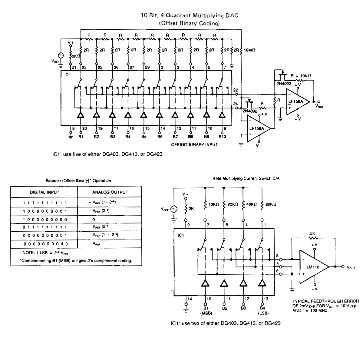
The following application circuits are designed to demonstrate several key concepts: A 2 kΩ resistor should be placed in series with the voltage source to limit supply current and mitigate negative ringing on the bit inputs. Temperature compensation for...
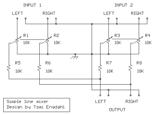
The mixer circuit described features three line inputs and three microphone inputs. The microphone inputs are designed for low impedance dynamic microphones with a range of 200 to 1000 ohms. Alternatively, an electret condenser microphone (ECM) can be used,...
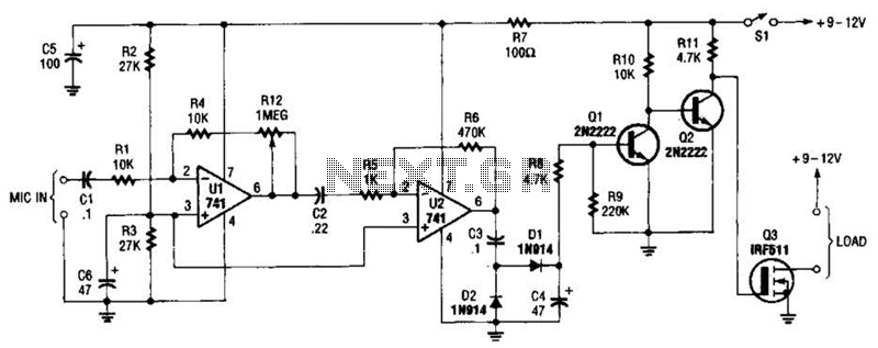
The audio-controlled switch utilizes a pair of 741 operational amplifiers, two 2N2222 general-purpose transistors, a hexFET, and several supporting components to create a circuit capable of activating devices such as a tape recorder, a transmitter, or virtually any other...
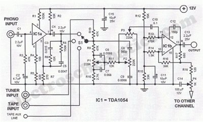
This Hi-Fi stereo preamplifier circuit is constructed using the TDA1054 integrated circuit (IC) from SGS. The TDA1054 is housed in a 16-pin DIL package and incorporates two separate preamplifier circuits. It is characterized by low noise and minimal issues...