
Audio Light Modulator
The audio light modulator circuit is designed to synchronize light effects with audio signals, creating a dynamic visual experience that complements music playback. This circuit typically utilizes a microphone or audio input to detect sound levels, which are then processed to control the brightness and color of connected lights, such as LEDs or incandescent bulbs.
The essential components of this circuit include a microphone or audio input stage, an amplifier, a rectifier, and a light control output. The microphone captures ambient sound, converting it into an electrical signal. This signal is then amplified to ensure that it is strong enough for further processing. The rectifier converts the AC signal from the audio source into a DC signal, which is necessary for controlling the light output.
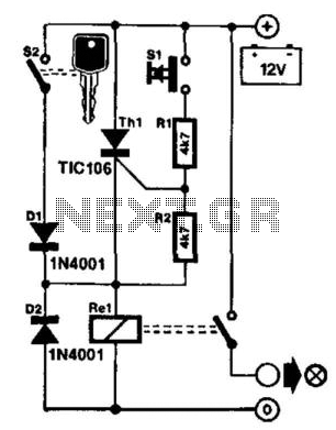
A key feature of the audio light modulator is the use of a transistor or a triac, which acts as a switch to control the power delivered to the light source. By adjusting the duty cycle based on the audio signal's amplitude, the circuit can vary the light intensity in real-time, creating a pulsing effect that corresponds to the rhythm and dynamics of the music.
In summary, the audio light modulator circuit provides an engaging way to enhance musical experiences by integrating visual elements. Its simplicity makes it accessible for hobbyists and can be easily adapted for various applications, including parties, concerts, and home entertainment systems.Audio Light Modulator. Audio light modulations add to the enjoyment of music during functions organised at home or outdoors. Presented here is one such simple circuit in which. 🔗 External reference
Related Circuits
This circuit is utilized in a multiplier that operates with one of the operational amplifiers in an analog computer. The double-triode V1 in this configuration provides pulse-amplitude modulation, which is intended for use with a separate pulse-width modulator to...
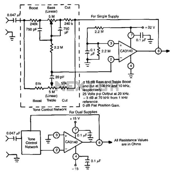
This circuit utilizes the high slew rate, high input impedance, and high output-voltage capability of the CA3140 BiMOS operational amplifier. It also offers mid-band unity gain using standard linear potentiometers. The circuit design leverages the characteristics of the CA3140 BiMOS...
The power failure light that I eventually designed and built is housed in the plastic case from a wall-mounted power transformer. I had accidentally destroyed the transformer by shorting its output, and had kept the plastic case for years,...
It is frustrating to discover that the car headlights have been left on, resulting in a dead battery. One solution to this problem is the proposed control circuit. This circuit does not issue a warning; instead, it takes action:...
The circuit of automatic emergency light presented here has the following features: 1. When the mains supply (230V AC) is available, it charges a 12V battery up to 13.5V and then the battery is disconnected from the charging section....
Without a dedicated buck converter or white LED driver IC, it is possible to safely drive multiple standard high-efficiency white LED modules using available battery power. To design a circuit capable of driving high-efficiency white LED modules without a dedicated...