
LED Power Failure Light
If we take the circuit node that is represented in the schematic by the lower AC line input to be our reference, I can talk about the upper connection shown in the schematic -the one that F1 is connected to, as having the full AC power line voltage on it with respect to our reference, and it will be a lot easier to describe the circuits operation.
Under normal operation, a little while after power is first applied to the circuit, the AC voltage from the power line sees R1, the 20 Ohm resistor in series with C1, R3, and the combination of D1, D2, and D3. The 24 volt Metal Oxide Resistor (MOV) does not conduct in normal operation.
The RMS current through the input circuit is approximately equal to the input voltage divided by the series impedance. Impedance is equal to the square root of resistance squared plus the reactance of C1 squared. The reactance of C1 is 1/(6.28 x 50 x .000000068) = 47,000.
This is very large compared to the resistance, which is dominated by the 20 Ohm resistor, so as a practical matter, we can say that current is equal to the input voltage divided by the reactance (47k) of C1.
The RMS current, in amps, is equal to 240 VRMS / 47k = 5 milliamps RMS. Since average current is equal to 0.9 times RMS current, the total average current available to trickle charge the battery and keep C2 charged up is 4.5 milliamps.
Since most of the voltage is dropped across C1, the current is practically independent of the state of charge on the battery, B1.
A few critical words on the election of components for this part of the circuit. The key safety components are C1, R1, and F1. C1 is an X type capacitor. X type capacitors meet certain safety specifications and are designed to be safely used across the AC power line. Other types of capacitors may fail from the constant AC power line voltage across it, and when they fail, the results could be deadly. Don't use other types of capacitors. The reason that C1 is a .068 uf capacitor is that this is the largest value X capacitor that I could get my hands on.
A review of safety capacitors can be found at the URL below (you should be able to click on URL -just remember to come back here!): http://www.justradios.com/safetytips.html
F1 is there just in case C1 does short out. I feel that, although the likelihood of C1 failing as a short are extremely remote, that to me, its worth the small cost of the fuse to provide a little additional peace of mind.
Relevant to C1, R2, and R3 are across C1 to bleed off the charge on C1 so that I won't get shocked if I touch the power failure light's AC line contacts. The time constant is only 1.4 Meg Ohms x .068 uf = 0.1 second, so the voltage would bleed down to less than 5 volts in about half a second. The reason I used two resistors in series instead of just using a single 1.5 Meg Ohm resistor was to assure that there was sufficient margin in the resistor's voltage rating. The resistors I used were nonflammable 1/4 carbon film type.
R1 is there to limit the maximum current when the power failure light is first plugged into the AC line. Since the RMS voltage is 240 volts, the maximum peak voltage across the input is 240 volts x 1.414 = 340 volts peak. If the power plug makes contact with the AC line at the instant the power line is at 340 volts. Since C1 is discharged when the power failure light is first plugged into the AC line, and the MOV clamps voltage at about 24 volts, the maximum current through R1 and the MOV (Z1) is approximately (340V - 24V) / 20 Ohms = 16 amps. Without R1 the current would be very high, and a small fraction of that current could damage one of the semiconductors in the circuit if, by chance of a ground loop, some of that current were to get into other parts of the circuit. It also keeps the sparks down when you plug the power failure light into the wall.
The power failure light circuit is designed to provide illumination during power outages while ensuring safety through the use of protective components. The circuit utilizes an AC line input for power, which is transformed into a low current output suitable for charging a rechargeable battery. The system incorporates a trickle charging mechanism to maintain battery charge, allowing the light to function as a portable flashlight when needed.
Key components include the X type capacitor C1, which provides safety against electrical failure, and the fusible resistor R1, which acts as a current limiter during initial power application. The Metal Oxide Varistor (MOV) safeguards the circuit by clamping excess voltage, ensuring that sensitive components are protected from surges. Resistors R2 and R3 serve to discharge the capacitor safely, preventing accidental shocks.
The overall design reflects a balance between functionality and safety, with careful consideration given to component selection to mitigate risks associated with AC powered devices. The circuit's operation is characterized by low current draw, ensuring prolonged illumination during outages while maintaining a compact and user-friendly form factor.The power failure light that I eventually designed and built is housed in the plastic case from a wall-mounted power transformer. I had accidentally destroyed the transformer by shorting its output, and had kept the plastic case for years, just waiting for a project like this one.
Since its mounted in a hand-sized enclosure, when the power fails, it is a simple matter to walk over to the light, unplug it from the wall, and use it like a flashlight to walk into other rooms to retrieve a flashlight. This particular lamp dims after a few minutes, and is down to a dull glow after about 15 minutes. The glow can last for hours after that. I suspect that this is at least partly the result of using rechargeable batteries from a surplus store.
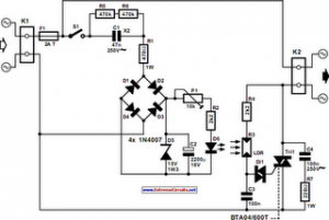
The first thing you should notice about the AC Line Input and Trickle Charging Circuit is the fuse. Not only one fuse, but two, because R1 is a fusible resistor. I'm pretty concerned about personal electrical and fire safety, especially when it comes to AC line operated devices in my home. I'll come back to the fuse later, but first, a little bit about how the circuit works. If we take the circuit node that is represented in the schematic by the lower AC line input to be our reference, I can talk about the upper connection shown in the schematic -the one that F1 is connected to, as having the full AC power line voltage on it with respect to our reference, and it will be a lot easier to describe the circuits operation.
Under normal, operation, a little while after power is first applied to the circuit, the AC voltage from the power line sees R1, the 20 Ohm resistor in series with C,1 R3, and the combination of D1, D2, and D3. The 24 volt Metal Oxide Resistor (MOV) does not conduct in normal operation. The RMS current through the input circuit is approximately equal to the input voltage divided by the series impedance.
Impedance is equal to the square root of resistance squared plus the reactance of C1 squared. The reactance of C1 is 1/(6.28 x 50 x .000000068) = 47,000. This is very large compared to the resistance, which is dominated by the 20 Ohm resistor, so as a practical matter, we can say that current is equal to the input voltage divided by the reactance (47k) of C1. The RMS current, in amps, is equal to 240 VRMS / 47k = 5 milliamps RMS. Since average current is equal to 0.9 times RMS current, the total average current available to trickle charge the battery and keep C2 charged up is 4.5 milliamps.
Since most of the voltage is dropped across C1, the current is practically independent of the state of charge on the battery, B1. A few critical words on the election of components for this part of the circuit. The key safety components are C1, R1, and F1. C1 is an X type capacitor. X type capacitors meet certain safety specifications and are designed to be safely used across the AC power line.
Other types of capacitors may fail from the constant AC power line voltage across it, and when they fail, the results could be deadly. Don't use other types of capacitors. The reason that C1 is a .068 uf capacitor is that this is the largest value X capacitor that I could get my hands on.
A review of safety capacitors can be found at the URL below (you should be able to click on URL -just remember to come back here!): http://www.justradios.com/safetytips.html F1 is there just in case C1 does short out. I feel that, although the likelihood of C1 failing as a short are extremely remote, that to me, its worth the small cost of the fuse to provide a little additional peace of mind.
Relevant to C1, R2 and R3 are across C1 to bleed off the charge on C1 so that I won't get shocked if I touch the power failure light's AC line contacts. The time constant is only 1.4 Meg Ohms x .068 uf = 0.1 second, so the voltage would bleed down to less than 5 volts in about half a second.
The reason I used two resistors in series instead of just using a single 1.5 Meg Ohm resistor, was to assure that there was sufficient margin in the resistor's voltage rating. The resistors I used were nonflammable 1/4 carbon film type. R1 is there to limit the maximum current when the power failure light is first plugged into the AC line.
Since the RMS voltage is 240 volts, the maximum peak voltage across the input is 240 volts x 1.414 = 340 volts peak. If the power plug makes contact with the AC line at the instant the power line is at 340 volts. Since C1 is discharged when the power failure light is first plugged into the AC line, and the MOV clamps voltage at about 24 volts, the maximum current through R1 and the MOV (Z1) is approximately (340V - 24V) / 20 Ohms = 16 amps.
Without R1 the current would be very high, and a small fraction of that current could damage one of the semiconductors in the circuit if, by chance of a ground loop, some of that current were to get into other parts of the circuit. It also keeps the sparks down when you plug the power failure light into the wall. 🔗 External reference
Related Circuits
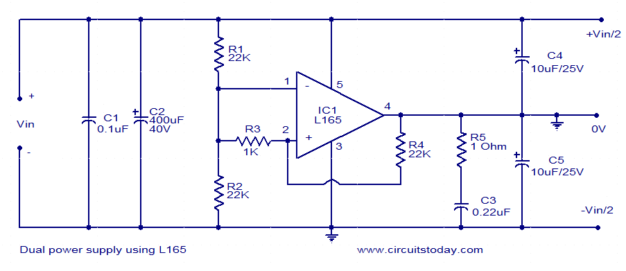
This dual power supply utilizes the L165 power operational amplifier from SGS-Thomson Microelectronics. The L165 IC can deliver up to 3.5A of current, with internal current limiting. It is available in a Pentawatt package, making it well-suited for power...
The following circuit illustrates a power supply for an amplifier circuit diagram. Features include ease of construction and adequate electrical response. The power supply circuit for an amplifier is a crucial component that ensures the amplifier operates effectively. It typically...
This circuit allows a 12v relay to operate on a 6v or 9v supply. Most 12v relays need about 12v to "pull-in" but will "hold" on about 6v. The 220u charges via the 2k2 and bottom diode. When an...
The following circuit illustrates an Automatic Light Dimmer Circuit Diagram utilizing a 1N4007 diode. Features include integration within a wall-mounted box. The Automatic Light Dimmer Circuit is designed to adjust the brightness of a light source automatically based on ambient...
This instructable demonstrates how to create low-power wireless charging circuits that facilitate the transfer of energy without direct electrical connections. Wireless charging circuits utilize electromagnetic induction to transfer energy between two coils, typically referred to as the transmitter and receiver...
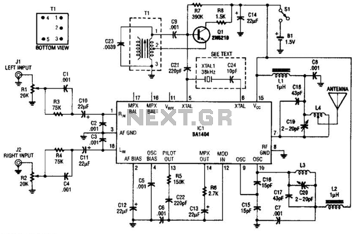
In this application, a BA1404 is utilized to generate an FM MPX baseband signal. This signal modulates a crystal oscillator (Q3) through a dual varactor series modulator. This transmitter can be used to play CD audio on an existing...