
Audio Peak / Beat LED indicator
The circuit described functions as a noise indicator for audio systems, specifically designed to monitor and prevent potential damage to speakers caused by excessive noise power levels. The key component of this circuit is the adjustable potentiometer P1, which allows the user to set a specific threshold for noise detection. When the noise level exceeds this threshold, the LED indicator D1 is activated, providing a visual cue to the user.
The circuit includes two resistors, R1 and R2, which serve to set up the biasing conditions for the transistor T1 (2N3904). Resistor R1 is specified as 680 ohms, and R2 is 1.2 kOhm, which together form a voltage divider that helps in controlling the base current of the transistor. The transistor acts as a switch that can be used to control additional circuitry, such as a relay or an opto-coupler, to disconnect the signal path to the speakers when excessive noise is detected.
The power supply for the circuit can be provided by a bridge rectifier (B1), which can be either a B250C1000 or a configuration of four 1N4003 diodes. This ensures that the circuit operates efficiently with a stable DC voltage, which is essential for the reliable functioning of the LED and the transistor.
In terms of operation, the user can experiment with different values of P1 to adjust the sensitivity of the noise detection. A linear potentiometer of 100 kOhm has been chosen, but variations may yield different performance characteristics. If additional isolation or control is desired, the circuit can be modified to include an opto-coupler for signal switching or a relay to physically disconnect the speakers from the audio path, thus preventing any potential damage.
Overall, this circuit design serves as an effective means of safeguarding audio equipment from noise-induced damage while providing a simple yet functional user interface for monitoring audio levels.This indicator can be used, or see if your speakers can be damaged by the noise power. With P1 you can set the limit to which D1 LED lights. The pot is 100k here, you can even experiment with other values. If you are a logical port on the switch or LED is an opto coupler would use it so you can switch the signal between the preamp and power amp would fall off. Or that the signal to the speakers using a relay would be removed. Parts List R1 = 680 ? R2 = 1.2 kOhm P1 = 100 kOhm linear B1 = B250C1000 or 4 x 1N4003 D1 = LED T1 = 2N3904 🔗 External reference
Related Circuits
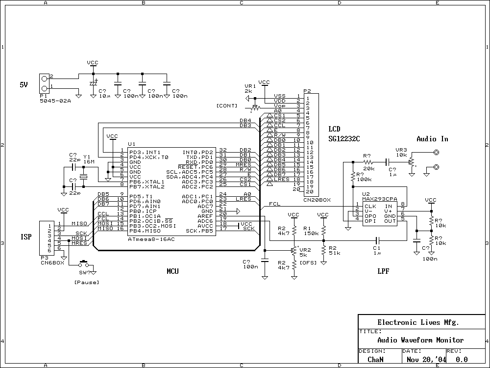
This is an evaluation use of a small graphics LCD module. Last summer, SG12232C graphic LCD module has been sold for 1500 Yens from Akizuki Denshi and I bought it. However, I could not find a good application for...

This application note explains how to implement a 2.1 (satellite/subwoofer) audio power-amplifier system with 2 x 2W and 1 x 7W of output power from a single 5V power supply. The described 2.1 audio power-amplifier system is designed to deliver...
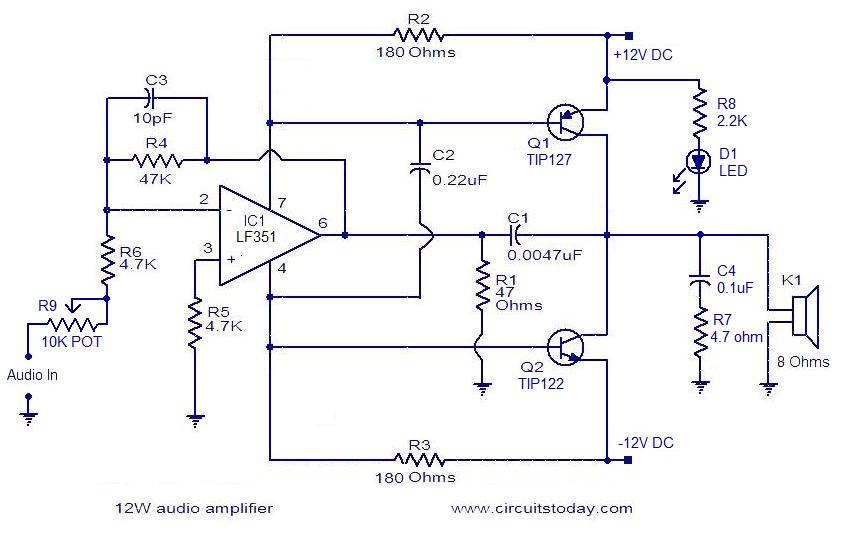
The circuit presented is a simple audio amplifier capable of delivering 12W to an 8 Ohm speaker. The operational amplifier IC TL081 serves as the preamplifier in this design. Alternatively, any operational amplifier with compatible power supply ratings can...
The short circuit-proof outputs of amplifiers and speakers present intriguing features, including the isolation of the speakers from the amplifier output. The design of short circuit-proof outputs in amplifiers and speakers is crucial for ensuring system reliability and longevity. Such...
The circuit below demonstrates how to power one or two LEDs from a 120-volt AC line. It utilizes a capacitor to reduce the voltage and a small resistor to limit the inrush current. As the capacitor needs to allow...
Anyone who has ever dealt with construction of low-voltage-fed inverter realized that this is no easy task. The shrinking supply voltage decreases rapidly transferred power and efficiency. Samokmitající converters fail to provide sufficient power to drive control for the...