
Audio remote control switch schematic
The audio remote control system described utilizes a Phase Locked Loop (PLL) circuit to achieve precise frequency detection and switching capabilities. The CD4046 PLL chip serves as the core of this system, integrating essential components such as a phase comparator, low-pass filter, and voltage-controlled oscillator (VCO). The phase comparator plays a critical role in comparing the frequency of incoming audio signals with a reference frequency generated internally. This comparison enables the system to maintain synchronization between the detected sound and the internal oscillator, thereby facilitating accurate control operations.
The circuit's robustness against environmental interference is a significant advantage, as it can filter out unwanted noise and respond only to specific frequencies, such as those produced by a whistle. The design incorporates feedback mechanisms that adjust the oscillator's frequency, ensuring that it remains locked onto the desired signal even in the presence of competing sounds.
In practical applications, the microphone (BM) captures the audio signals, which are then amplified and processed by the PLL circuit. The output from the PLL circuit is used to control a switch, enabling or disabling connected devices based on the detected audio frequency. The system's effectiveness can be enhanced through careful tuning of the receiving circuit, allowing for optimal sensitivity and range. This feature makes the audio remote control suitable for various applications, including remote activation of devices in environments where traditional remote controls may be ineffective.
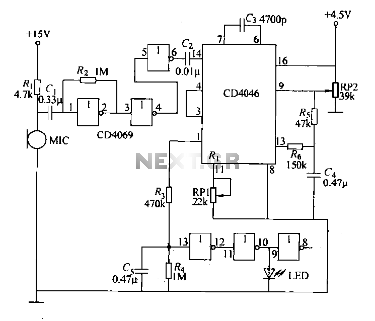
Overall, the combination of the CD4046 PLL circuit, audio amplification, and precise frequency detection creates a reliable and efficient audio remote control system capable of functioning effectively in diverse conditions.Each issue a specific frequency of sound, audio remote control will switch changes state, the circuit for other frequencies emitted by the environment sound with strong anti-in terference ability. (1) circuit principle 1) phase locked loop circuit principle: CD4046 PLL circuit includes a phase comparator, a low-pass filter and a voltage controlled oscillator section 3 group into. The phase comparator function is outside the sound signal with the center frequency of the internal pulse signal frequency comparison + when the same frequency, the output from the first O feet high potential; whether it is internal or external sound signal oscillation signal whose frequency It will have to unlock like state.
In order to solve this. Problem, phase-locked loop circuit through the filter of the phase comparator output voltage feedback voltage to the oscillator to change the frequency of the internal oscillator pulses, so that the frequency of the external signal is the same; that starting from the unlock state to the final Lou set of allowed state of the input signal frequency range is called the frequency capture range. CD4046 pin shown in Figure 18-43a. CD4069 hex inverter pin diagram shown in Figure 18-43b. Fig. 1 PH11 signal input; PHlZ the comparison signal input terminal {VC01 for the VCO control terminal; INH to prohibit the end; Z is the internal zener negative terminal} DEMo demodulated output terminal; R2, Rz is external resistor end; G, G for the external capacitor end; PH01, PH02 for the phase comparator - Guo ln} PH03 output of the phase output terminal, when the lockup high, low loss of lock when almost; vCOo as a voltage controlled oscillator output terminal 2) principle analysis: circuit can whistle sound as a transmission signal, the remote control.
Received by the microphone BM, adjusting circuit receiving frequency, so that the circuit only respond to a specific whistle sounds. Carefully adjusted so that the circuit the highest sensitivity, control distances. As if the producers have more experience, you can also use the mouth blowing a whistle to adjust the circuit.
Receiving circuit shown in Figure 18-43c. Hex inverter circuit by the CD4069 and CD4060 14 in hex serial counter/divider and other components audio amplifier circuit, PLL circuit and a switch output circuit. Audio amplifier sound microphone signal was subjected to amplification. External sound signal after amplification to the input of the PLL circuit. PLL has an internal voltage-controlled oscillator, flat while working on the set operating frequency.
When the external audio signal successor PLL circuit, and every time it receives the VCO operating frequency when the same audio signal, phase locked loop circuit is in a locked state, the voltage output of the circuit changes from low to high, the output of the control switch circuit change switch status.
Related Circuits
This circuit activates a lamp at a remote location when the doorbell switch is pressed. It is designed specifically for solenoid-type doorbells, as electronic doorbells that play tunes are incompatible. The circuit addresses the issue of potentially missing the...
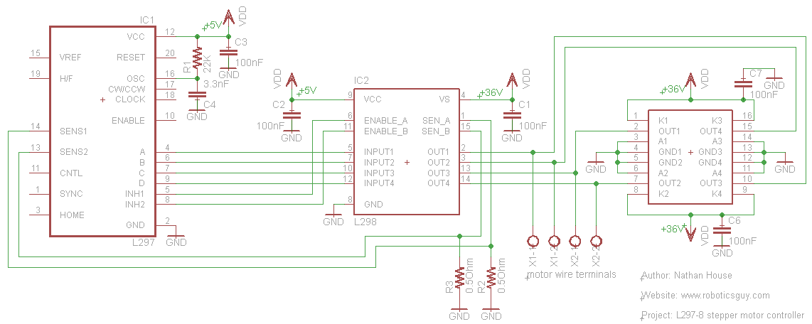
An efficient method for constructing a stepper motor controller involves creating a printed circuit board (PCB) and then placing the components onto it. Once the PCB is fabricated, the assembly and soldering of components is a quick process, especially...
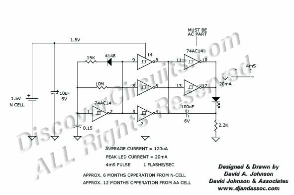
Many published circuits that flash LEDs require 3 volts or more. This circuit utilizes a single inexpensive C-MOS IC and can flash an LED for an entire year on a single 1.5-volt AA alkaline battery cell. The circuit employs...
Integrated circuits (ICs) have largely replaced traditional circuits like this one; however, this circuit is still utilized where the flexibility of a discrete device design is desirable. The components are readily available, and the issue of IC obsolescence is...
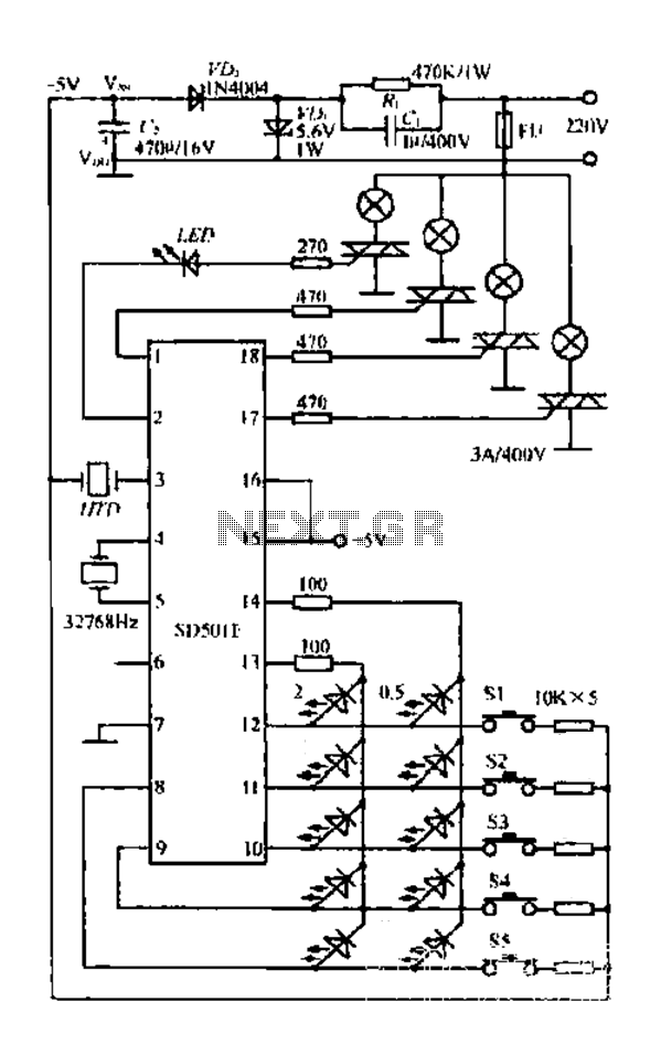
The FIG SD501E is a J tie fan integrated circuit (IC) characterized by progressive timing and three operational modes: strong, medium, and weak. It features three types of output settings and includes an electrical swing mechanism. The device is...
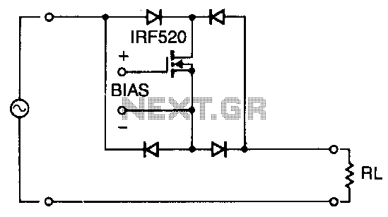
Utilizing four diodes in an array enables the use of a single MOSPOWER transistor for analog switching. The current flow is managed by maintaining the source-base connection of the MOSFET towards the load. It is essential to select diodes...