
Doorbell Warning Switch
This circuit serves as an effective solution for enhancing the visibility of a doorbell alert, particularly in environments where audio cues may be missed. The design incorporates a solenoid-type doorbell, ensuring compatibility and reliable operation. The inclusion of a series resistor, R1, is crucial; it limits the current flowing through the doorbell when the switch is engaged. The calculated voltage drop across R1 not only ensures that the transistor is activated but also minimizes power consumption, thereby prolonging the life of the power source.
The choice of resistors (22 ohms and 50 ohms in parallel) allows for a precise voltage drop that is tailored to the specific requirements of the circuit. This configuration enables the transistor to switch on effectively, allowing for the lamp to illuminate brightly when the doorbell is pressed. The electromechanical counter adds an additional layer of functionality, providing a count of the number of times the doorbell has been activated, which can be useful in monitoring visitor frequency.
Overall, this circuit design is a practical enhancement for doorbell systems, integrating visual indicators and counters while maintaining energy efficiency. Proper selection of components and careful consideration of circuit parameters are essential for achieving optimal performance and reliability.This circuit will light a lamp at a remote location when the doorbell switch is pressed. This circuit should only be used with the solenoid type doorbells, the electronic type that play tunes will not work here. It is quite easy to miss the sound of a doorbell if you are watching TV, this circuit gets round the problem by providing a visual indic
ation. As an alternative, a LED could also be used. You could just parallel a lamp across the doorbell, but this would mean extra drain from the doorbell batteries or transformer. A series resistor, R1 is wired in series with the doorbell and reduces current flow, thereby increasing battery life.
The value of R1 is chosen so that about 0. 6 to 0. 7 volts is developed across it, when the doorbell switch is pressed. I used a combination of a 22 ohm resistor in parallel with a 50 ohm. The voltage drop across R1 is sufficient to switch on the transistor, the lamp in series with the collector will then illuminate. I also used an electromechanical counter in parallel with the lamp. 🔗 External reference
Related Circuits

In this modern era, any relationship characterized as master/slave may raise ethical concerns; however, for this circuit, it effectively illustrates its operation. The circuit detects the mains current supplied to a master device and controls the on/off state of...

Touching the on contacts with a finger brings pin 3 high, turning on the Darlington pair and supplying power to the load (transistor radio, etc.). Q1 must be a high-gain transistor, and Q2 is chosen for the current required...

By incorporating discrete inductors in series with the device, it is possible to "tune out" some of the capacitance and enhance the eye opening. By adding sufficient inductance to peak the third harmonic at 240 MHz, while considering the...

This is a small circuit designed for use as a charging controller or voltage limiter. It is particularly useful for creating a solar charger. The assembly of the circuit allows for modifications according to personal preferences. The circuit is...

High-voltage isolation switches must not be connected to loads that could create an arc, which may lead to a short circuit between the high-voltage bus and result in accidents that endanger both equipment and personnel safety. Consequently, high-voltage switchgear...
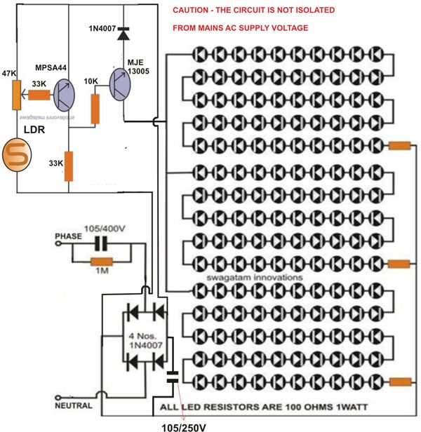
At times, it is quite frustrating to see street lights remaining switched on even during broad daylight. The current circuit for an automatic night light can effectively address this issue. This article explains how to construct such a system....