
Audio Response with the FT8900 Yaesu MH-48A6J

The modification process described involves several key steps to enhance the performance of the microphone used in conjunction with a radio system, specifically addressing low-frequency response issues. The careful removal of the microphone element and the drilling of holes to create a slot are essential for accessing the internal components. The addition of cotton serves a dual purpose: it acts as a pop filter to reduce plosive sounds while also dampening resonances that can affect audio clarity.
The critical aspect of this modification lies in the audio path alteration. The existing high-pass filter created by the 0.1 µF capacitor and 1 kΩ resistor restricts low-frequency signals, which can adversely affect speech intelligibility. By bridging a tantalum capacitor from the microphone output to pin 5, the modification effectively bypasses the high-pass filter, allowing a broader range of frequencies to pass through.
The choice of a tantalum capacitor is significant due to its favorable characteristics, such as stable capacitance and reliability in audio applications. Proper soldering techniques are vital to ensure a secure connection without damaging the small components on the circuit board. The use of double-sided foam tape adds an additional layer of stability to the capacitor, preventing movement that could lead to connection issues over time.
This modification not only enhances the audio output of the microphone but also improves the overall performance of the radio system, making it a valuable upgrade for users seeking better sound quality.Gently work a small screw driver around the mic element rubber boot, and slowly work it out from the mic front casing. Be gentle and take your time. I found that there was a spot near the top of the mic housing where I could work the screwdriver in to get things started.
Lift the mic element out of its housing when you have it loosened up. 9.Using a 1/16 inch drill bit, drill out the two existing holes in the front of the microphone and the third fake one. Then slide the drill bit back and forth to transform the three holes into a slot. (See the picture below for an idea of how this will look when you are done. ) 13. Wad up a tiny bit of cotton and place it inside the mic housing where the baffle was. Use enough to loosely cover the bottom of the little chamber that houses the electret. This helps to act as a pop filter. Using too much may result in a muffled sound, you really just need a few wisps. 15. Mount the circuit board inside the front of the microphone and tighten down the screws. Then wad some cotton to fill the mic housing. This microphone seems to have some odd acoustic resonances from the hollow space in the back of the microphone. The cotton will reduce this effect greatly. The worst culprit regarding restriction of the low end audio appears to be in the speech amplifier built into the remote display head of the radio.
A circuit diagram for the PANEL-SUB-UNIT is located on the back of the MAIN UNIT block diagram. One glance will reveal that they have coupled the output of the mic through a. 0056 uf capacitor to the input of the first stage of the speech amp. A larger value would have produced much smoother response, and much more audio. However, this circuit board is populated with devices that are the size of a flea, and I would not even attempt to mess with it! All is not lost though, you can still bring about some improvement right in the microphone unit itself.
If you examine the schematic below, and trace the audio path from the output of the electret mic element to pin 5 of the connection plug for the mic cord, you will see why the low end response of this microphone is so restricted. The 0. 1uf capacitor (C5003) in parallel with the 1k resistor forms a high pass circuit that effectively blocks the passage of a good percentage of the normal low end voice frequencies.
The easiest way around this is to simply bridge a cap from the mic output to pin 5. All the RF bypassing and decoupling will still work effectively, but the audio path will now bypass the 0. 1uf (C5003) frequency shaping capacitor and the 0. 33uf (C5002) coupling cap. I chose a tantalum 10uf cap (RS part number 272-1436) for this task. This will boost the low end frequency response and also raise the total audio output of the mic slightly, which in my opinion is a good thing because the FT8900 seems a little lean in that department with the stock setup.
Directions for completing this modification are below. Examine the picture below to see where the two solder connection points are. It is important to pay attention to the polarity of the cap as you are connecting to the voltage feedpoint of the mic element. In the picture below, the plus lead of the cap is soldered to the left side of the cap labeled V104 (C5003) and the other leg is soldered to the right side of the cap labeled V334 (C5002).
I placed a chunk of double sided foam tape behind the cap to help hold it steady when soldering and to prevent the cap from vibrating or stressing the solder points after the mic is put back into service. After bending the leads of the cap to fit, tin the leads with a low wattage iron using a very sharp tip.
Then press it into place. When the cap is in position, solder it to the pads at the ends of the surface mount devices. You won`t need much solder, and don`t linger on those tiny solder pads for too long! The final step to raising the audio level of the FT8900 involves accessing the ser 🔗 External reference
Related Circuits

During the recent audio hackers meetup at Hacker Dojo, discussions were held with Laura and Kevin regarding the challenges faced in creating a small local network referred to as "JamLan." There was mention of the consideration to develop a...
With the amount of equipment in home entertainment centers today the need to be able to vary the gain of the audio or video signal is needed. I found this particular circuit helpful when used in conjunction with the...

This design circuit is for audio graphic equalizers, which are commonly found as commercial products, yet published circuits for them are quite rare. The circuit features a simple design that requires an operational amplifier (op-amp) to amplify the input...
The circuit is very simple and incorporates darlington output transistors that will provide more than enough output current than is needed to drive a 3-ohm speaker. The gain may be pre-set for a variety of input levels, making it...
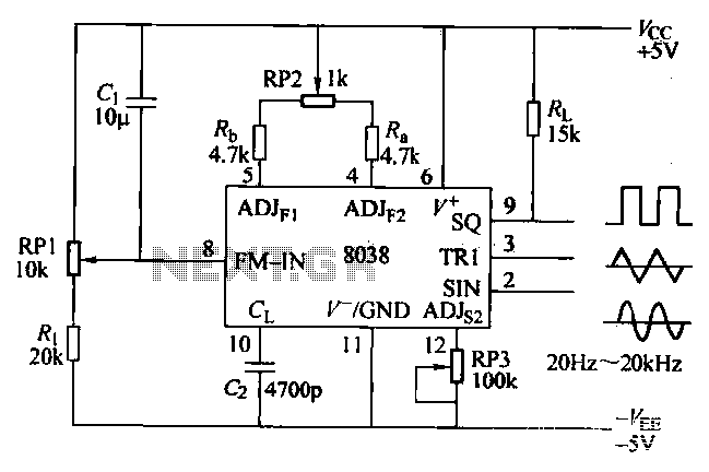
The ICL8038 function generator is an audio composition device that utilizes the ICL8038 integrated circuit. The resistance Ri potentiometer RP1 is used to determine the flow potential. Typically, the output is set to approximately 2Vcc / 3. Lowering the...
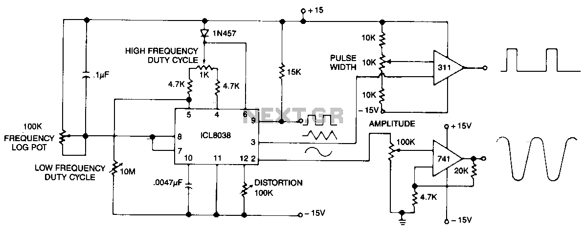
This circuit generates sinusoidal, square, and triangle waveforms simultaneously. The frequency can be set to a specific value or varied as indicated. An operational amplifier can be added for enhanced drive capability and simplified amplitude adjustment. Additionally, a simple...