
audio graphic equalizer circuit

The audio graphic equalizer circuit operates by dividing the audio frequency spectrum into multiple bands, each of which can be independently adjusted to enhance or attenuate specific frequencies. The use of gyrators in this design allows for the simulation of inductive behavior without the need for physical inductors, thus contributing to a more compact and cost-effective circuit.
Each gyrator stage is configured to respond to a specific frequency range, with the faders providing user control over the gain for each band. The operational amplifier plays a critical role in ensuring that the input audio signal is amplified sufficiently to drive the gyrators, which in turn manipulate the signal's frequency response.
The center frequency (f) for each band can be calculated using the provided formula, which takes into account the values of the capacitors and resistors in the circuit. The quality factor (Q) is essential for defining the bandwidth of each filter, with higher Q values resulting in narrower passbands. The relationship between Q and the capacitor ratio is crucial for achieving the desired frequency response characteristics.
The impedance calculation is vital for understanding how the circuit interacts with other components in the audio system. The resistive component ensures stability, while the capacitive and inductive terms allow for the tuning of frequency response. This comprehensive approach to circuit design enables the creation of effective audio graphic equalizers capable of delivering high-quality sound tailored to user preferences.This is a design circuit for audio graphic equalizers, that are very common as commercial products but circuits for them are very rarely published. This circuit is a simple design circuit. The circuit is needs an op-amp for amplifying the input signal. This is the figure of the circuit. Only one gyrator stage is shown: all 7 gyrators are the same circuit, only the capacitors change, as shown in the chart. I have shown three of the seven faders to show where they go. A gyrator is a circuit using active devices and transistors to simulate an inductor. In this case the gyrator is the transistor acting with R1, R3 and C2. It could just as easily be a unity gain op-amp. The circuit includes three formulae: one which gives f, the the centre frequency of the band. The second shows how the Q is related to the capacitor ratio. The third shows the impedance presented by the circuit. Note that this includes 3 terms, the first purely resistive, the second is the capacitive contribution from C1 and the third is an inductive term from the gyrator. 🔗 External reference
Related Circuits
The TDA8444 is a digital-to-analog (D/A) converter integrated circuit (IC) produced by Philips. It is designed to convert digital signals into analog signals. The TDA8444 IC utilizes a 16-pin dual in-line package, with specific pin functions and data outlined...
Parts List The circuit consists of a preamplifier, tone controls, and a regulated DC power supply, providing a power output of 18 Watts for an 8 Ohm load. The circuit design includes three main components: a preamplifier, tone control circuitry,...
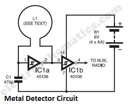
The metal detector circuit presented here exemplifies simplicity while demonstrating effective functionality. It utilizes a single 40106 hex Schmitt inverter IC, a capacitor, a search coil, and batteries. A connection from IC1b pin 4 must be made to a...
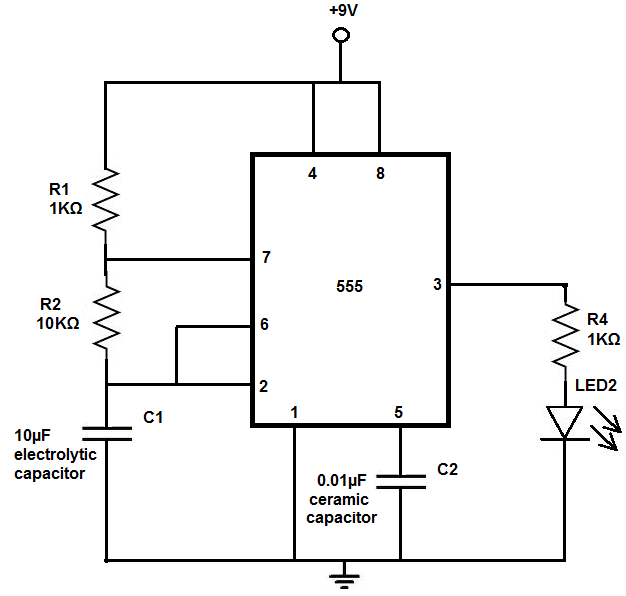
The 555 timer chip is a versatile integrated circuit (IC) that, when connected correctly, can generate pulses of current at specific intervals determined by a resistor-capacitor (RC) network. In this mode, the LED does not remain constantly lit; it...
This circuit measures the distance covered during a walk. The hardware is located in a small box that can be slipped into a pants pocket. The display is designed such that the leftmost display, D2 (the most significant digit),...
This is a schematic diagram of a stereo audio amplifier for a car. The circuit is powered by a single IC, the TDA1553, along with some external components. This IC is designed to manage the stereo car audio system....