
Audio Voice-Over Circuit using LM380
The microphone preamp circuit is essential in applications where clear voice communication is critical, such as in intercom systems, public address systems, and two-way radios. The circuit typically consists of a microphone, an operational amplifier (op-amp), resistors, capacitors, and a push-to-talk (PTT) switch.
In operation, the microphone captures sound waves and converts them into an electrical signal. This weak signal is then fed into the op-amp, which amplifies it to a usable level. The change-over switch allows the user to select between the microphone input and other audio sources. When the PTT switch is pressed, it activates the microphone circuit, ensuring that the voice signal is prioritized and clearly transmitted over any background audio.
The design may include additional components such as low-pass filters to eliminate high-frequency noise and ensure a clean audio output. Furthermore, careful consideration must be given to the power supply requirements of the op-amp to maintain optimal performance. Overall, this microphone preamp circuit is a vital component in achieving effective voice communication in various electronic systems.This circuit is a circuit diagram of a microphone preamp and circuits (voice circuit) has priority over any other audio signal. In its simplest form, the voice-over only the microphone unit and the change-over switch eating an amplifier, the output of the microphone has priority over the amplifiers audio signal when the push-to-talk switch is pressed
🔗 External reference
Related Circuits
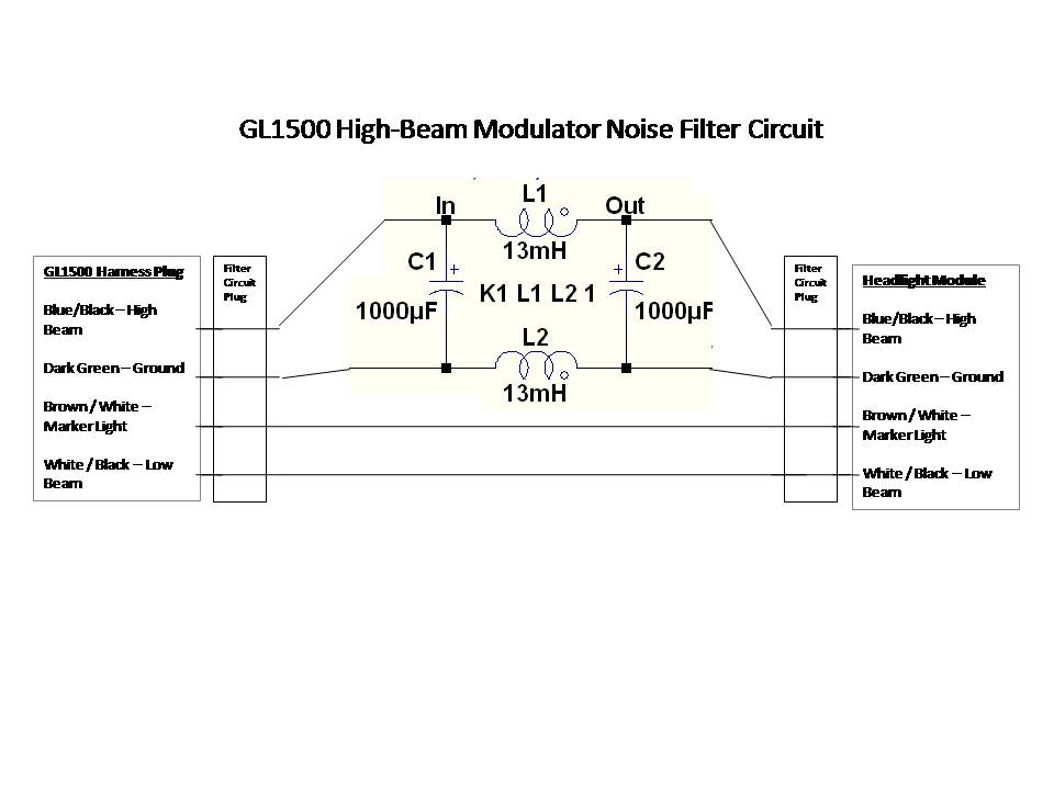
A power filter is a device that is placed before devices such as GPS, MP3 players, or radar detectors connected to the auxiliary circuit. When properly used and installed, these filters can eliminate modulator noise from any system. Observing...
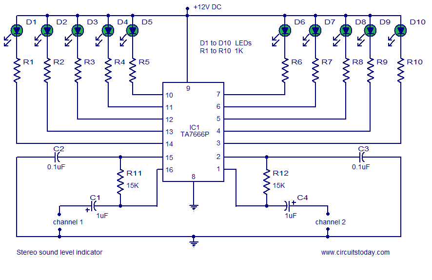
A stereo VU meter or 2-channel audio level meter utilizing the IC TA7666P. The volume level of each channel is indicated using 5 LEDs. This loudness meter requires a minimal number of external components. The stereo VU meter circuit is...
To make an LED function, a voltage source is required that exceeds the LED's forward bias voltage, which is typically greater than 1.5V (approximately 2V for red LEDs). To effectively operate an LED, it is essential to provide a voltage...
This solid-state push-pull single-ended Class A circuit is capable of providing sound quality comparable to that of valve amplifiers. It delivers an output power of 6.9W when measured across an 8 Ohm loudspeaker cabinet load, with reduced total harmonic...
Build a personal data logger for recording analog signals. The MiniLOGGER provides 8-channel analog input (-99mV to +999mV), 1-channel pulse input, battery backup with 256kB SRAM, a Real-time Clock, and RS232C communication. Recording can be initiated or stopped using...
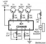
This is a simple home telephone ringtone generator circuit constructed using only a few electronic components. It generates a simulated telephone ringtone and requires a DC supply voltage ranging from 4.5V to 12V. This circuit can be used in...