
Single-ended Class A amplifier circuit diagram of 6N1 + 6P3P

The single-ended Class A tube amplifier circuit is characterized by its simplicity and effectiveness, making it an appealing choice for both novice and experienced audio enthusiasts. The 6N1 tube, utilized in the input stage, is known for its low noise and high gain characteristics, which help in achieving a rich and detailed audio signal. This tube operates in a linear region, contributing to the amplifier's warm tonal qualities.
In the power amplifier stage, the 6P3P tube is employed, which is renowned for its robust performance and ability to deliver a pleasing sound signature. The standard connection configuration for the 6P3P allows for efficient operation and reliable performance, making it suitable for entry-level applications. The design of the circuit should prioritize proper biasing and load matching to optimize the performance of the 6P3P tube, ensuring that it operates within its ideal parameters.
When constructing this amplifier, attention must be paid to the quality of components used, including resistors, capacitors, and transformers, as these elements significantly influence the overall sound quality. A well-laid-out PCB or point-to-point wiring can enhance the amplifier's performance by reducing noise and signal distortion.
Furthermore, the construction process should involve meticulous soldering and assembly practices to ensure durability and reliability. Adequate heat dissipation measures, such as heat sinks or ventilation, are essential for maintaining the longevity of the tubes and preventing thermal-related failures.
For enthusiasts embarking on this project, it is recommended to follow established schematics and guidelines, while also allowing for experimentation and personal touches in the design. This journey into tube amplifier production not only fosters a deeper appreciation for audio technology but also opens avenues for creativity and innovation in sound reproduction.Electronic tube amplifier lovers started his art that simple, excellent single-ended Class A circuit should be the first choice. Single-ended Class A tube amp with a mellow, sw eet and produced high success rate. This article describes the use of 6N1 lines constitute the input stage. Power amplifier stage 6P3P standard connection, 6P3P for entry-level product, the quality is quite outstanding, making the risk of low prices can minimize the same time as long as the line is reasonable design, careful production, but also can play 6P3P fever realm. More importantly, I wish to take this route, for those who just like a primary tube amp enthusiasts, by trying to become familiar with tube amp production.
Related Circuits
The LED Metronome is a contemporary version of a traditional device that is essential for music teachers, students, and composers. This circuit employs 12 LEDs to replicate the swinging motion of a pendulum, along with a speaker connected to...
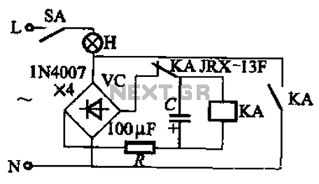
The circuit illustrated in Figure 13-3 consists of two configurations: (a) a DC power supply and (b) an AC power supply. Both configurations are utilized to control a relay. The flash frequency of the relay is determined by the...
This circuit is designed to achieve exceptional popularity, as evidenced by its record-breaking views and comments on the referenced website. As of May 3, 2013, it has garnered 760,191 views and 412 comments, with 116 views recorded on that...
This 18 dB gain amplifier was constructed using the Manhattan-style technique to assess the Linear Technology LT1253 dual video amplifier as a potential output amplifier for Direct Digital Synthesis (DDS) systems that utilize the Analog Devices AD9850 and similar...
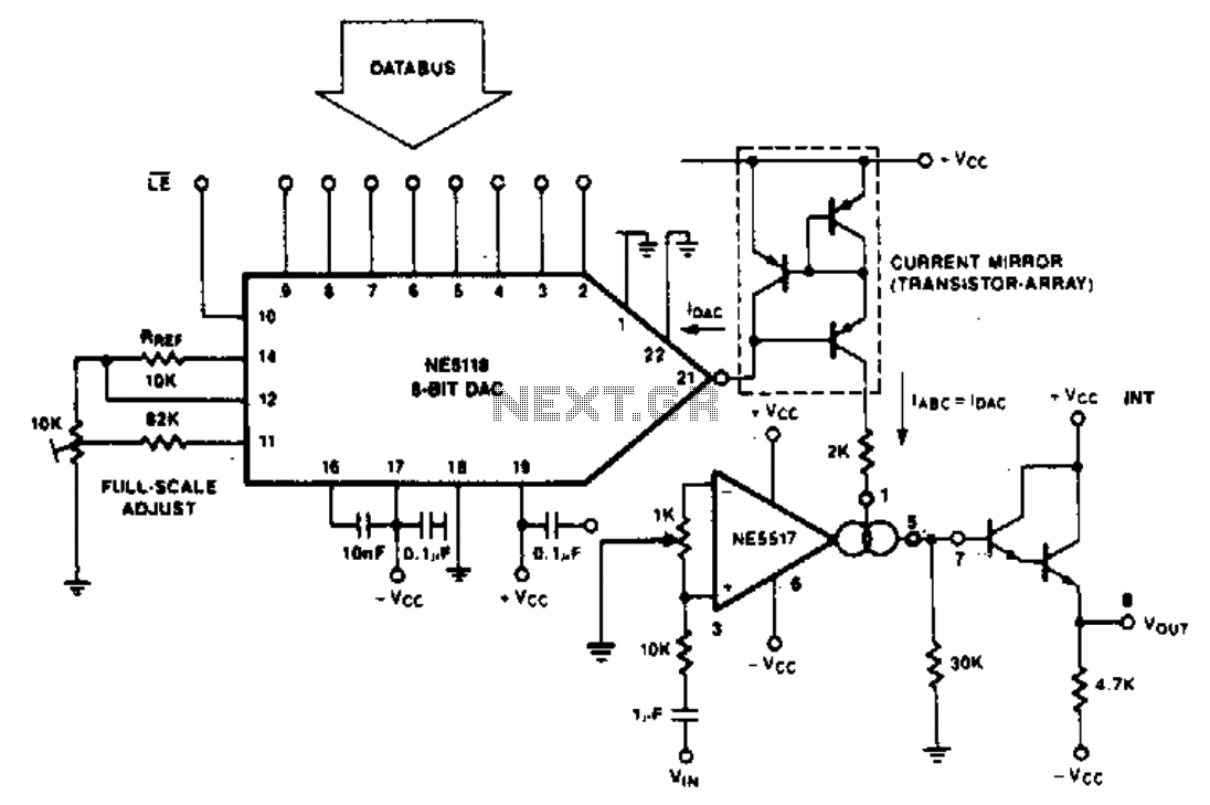
The purpose of the following application is to demonstrate how the NE5517 operates in conjunction with a DAC. The application utilizes the NE5118, an 8-bit DAC with current output, featuring an input register that makes this device fully micro-compatible....

SI and S2 must be pressed within 200 ms of each other to activate K1. The hold time is adjustable via K7. Additionally, the overlap time of SI and S2 can be modified by changing C1 and C2 or...