
Blinker circuit one b
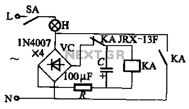
The circuit in Figure 13-3 demonstrates two distinct power supply options for relay control, which can be essential in various electronic applications. The first configuration, featuring a DC power supply, typically provides a stable voltage that can be easily regulated. This stability is crucial for applications where precise timing and control are necessary, as it ensures consistent relay operation without fluctuations.
In contrast, the second configuration employs an AC power supply, which introduces a different set of characteristics. AC power can be advantageous for certain relay types, especially those designed to operate with alternating current. The relay's activation in this scenario is influenced by the AC frequency, which can affect the timing and duration of the relay's operation.
The flash frequency of the relay is a critical parameter that defines how frequently the relay can switch on and off. This frequency is determined by the combination of resistance and capacitance in the circuit. The resistance (R) limits the current flowing through the circuit, while the capacitance (C) stores energy and influences the timing of the relay's activation. The relationship between these components can be expressed through the time constant τ (tau), which is calculated as τ = R × C. A higher resistance or capacitance results in a longer time constant, thus reducing the flash frequency. Conversely, lower values of R or C will increase the flash frequency, allowing the relay to operate more rapidly.
In practical applications, selecting the appropriate values for resistance and capacitance is essential to achieve the desired relay performance. The relay KA capacity must also be considered, as it indicates the maximum load the relay can handle without failure. This ensures that the relay operates within its specified limits, providing reliable performance in the intended application. Circuit shown in Figure 13-3. Figure 13-3 (a) DC power supply, Figure 13-3 (b) with AC power. They are used to control the relay. Flash frequency is determined by the resistanc e and capacitance C relay KA capacity.
Related Circuits
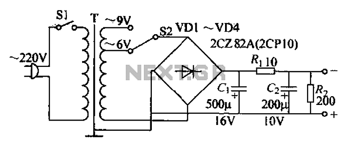
The adjustable current power supply circuit operates at 6V and 9V, utilizing a minimal number of components, which facilitates easy assembly. The circuit can deliver an adjustable output current of up to 100mA, serving as a suitable alternative to...
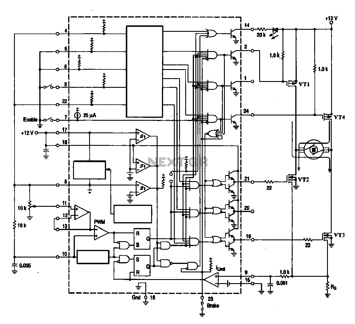
A DC brush motor driver circuit diagram utilizing the MC33035 chip is presented, illustrating a typical configuration for driving a straight DC brush motor. The circuit incorporates a field-effect transistor (FET) bridge driver setup. When transistor VT3 is activated,...
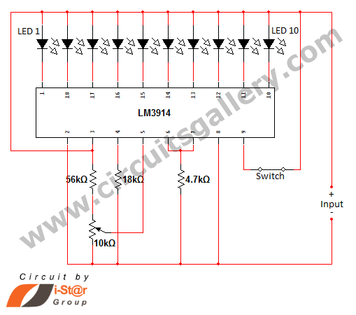
In various situations, it is necessary to indicate the amount of battery charge using methods such as LED dot displays or LED bar displays. This circuit utilizes the LM3914 integrated circuit to serve as a battery charge indicator with...
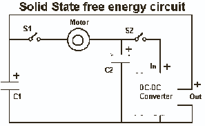
It's very simple actually. The idea is that we use what we have learned from the capacitor tests to create a circuit that uses the capacitors to run the load and then by discharging the 1/2 full capacitor into...
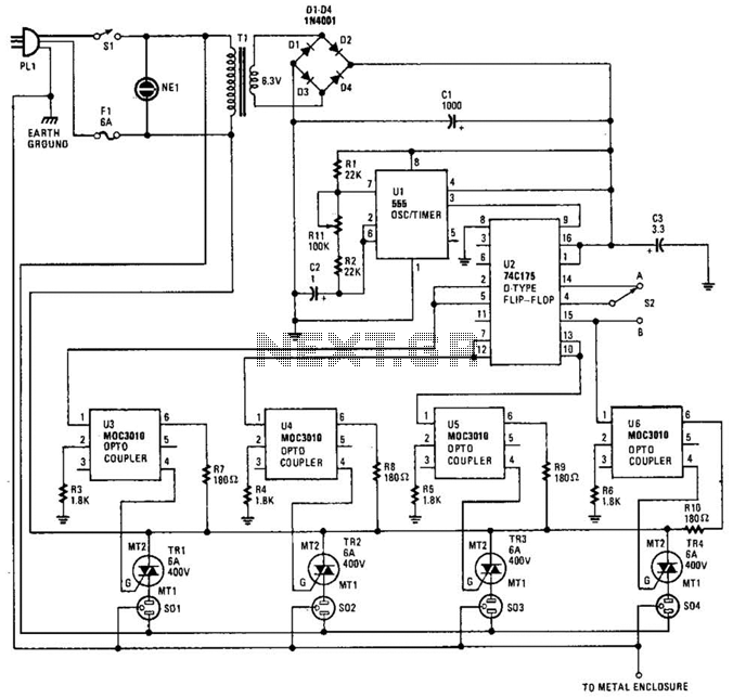
The integrated circuit U1 (a 555 oscillator/timer) is configured as a conventional pulse generator. The frequency of the pulse generator is adjusted using potentiometer R11. Resistor R2 limits the maximum frequency attainable. The output from the pulse generator is...
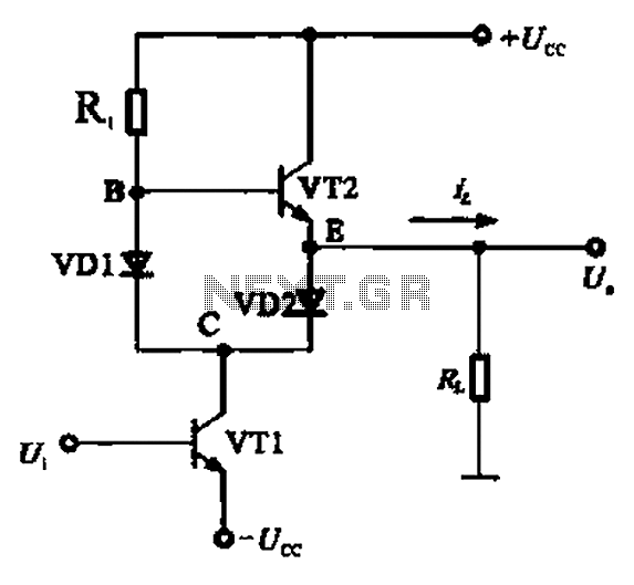
A Class AB output stage circuit is coupled with diodes, as illustrated in Figure 10-8. The static bias circuit for transistor VT1 (not shown) is adjusted so that the output at point E is at ground DC voltage UE....
Warning: include(partials/cookie-banner.php): Failed to open stream: Permission denied in /var/www/html/nextgr/view-circuit.php on line 713
Warning: include(): Failed opening 'partials/cookie-banner.php' for inclusion (include_path='.:/usr/share/php') in /var/www/html/nextgr/view-circuit.php on line 713