
Audison LR604XR car audio amplifier
The amplifier described utilizes a combination of bipolar transistors for amplification and FETs for the preamp and crossover stages, indicating a thoughtful design approach that optimizes both sound quality and reliability. The design reflects a high level of expertise, evident in the schematic layout, parts placement, PCB routing, and assembly processes, contributing to a low failure rate and high performance for a budget-friendly amplifier priced at approximately $50 per channel.
The LR series, which was the precursor to the Millenium series, was discontinued in 1999, suggesting that the design has stood the test of time, appealing to both audiophiles and casual listeners alike. The narrow heat sink design has influenced the overall shape of the PCB, necessitating a layout where the power supply and output stages are positioned on one side of the board. This strategic placement allows for efficient thermal management and minimizes potential interference between high-power and low-signal sections of the amplifier.
RCA inputs and crossover switches are located on the opposite side of the PCB, a logical arrangement that facilitates user access while maintaining signal integrity. The design also features acoustic output traces that run directly beneath the DC-DC transformer, a decision that may have implications for electromagnetic interference; however, the overall layout suggests that careful consideration has been given to minimize any adverse effects.
Overall, this amplifier design exemplifies a well-engineered approach to audio amplification, balancing performance, reliability, and cost-effectiveness within a compact form factor. The thoughtful organization of components and the choice of materials contribute to its reputation in the repair industry and among users seeking high-quality sound from an affordable device.If the amp is built on bipolar transistors, and the preamp/crossover on FETs, then they were designed by different guys, right? Not this amp. Here, a strong, experienced designer`s hand is evident from schematic to parts layout, PCB routing and general assembly.
Which leads to one of the lowest failure rates (don`t quote me on this although it`s common knowledge in repair industry) and a surprisingly good sound from a $50 per channel device. A unit worth a Web page. LR series - Audison`s junior - was formally discontinued in 1999, just to be repackaged under `Millenium` series name.
Narrow heat sink dictates board shape. Quite logically, power supply and power output are on one side, RCA inputs and XO switches on the other. Which also means that acoustic output traces run directly under DCDC transformer. Anyway, the form factor doesn 🔗 External reference
Related Circuits
The operating principle of the circuit is very simple. The first LED D1 is placed in series with the resistor R2 and diode D4. An only be lit this LED indicates that the battery is overcharged. For this reason,...
Approximately one watt RMS appears to be a suitable output level, which is also the maximum power that a basic amplifier powered by 12V can deliver to an 8 Ohm speaker. A very low saturation amplifier may reach up...
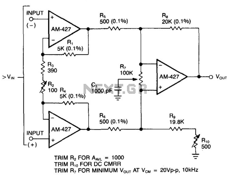
In a single difference amplifier configuration, the AM-427 demonstrates excellent common-mode rejection and low noise voltage, which is primarily influenced by the resistor Johnson noise. The three-amplifier configuration presented circumvents the low input-impedance characteristics typical of difference amplifiers. Due...
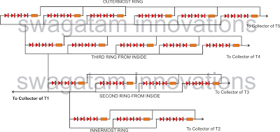
The following article outlines a sophisticated LED sequencing and diverging ring light that can serve as a tail brake light in vehicles. This circuit concept was proposed by a dedicated reader, Mr. Bobby. The design aims to create a...
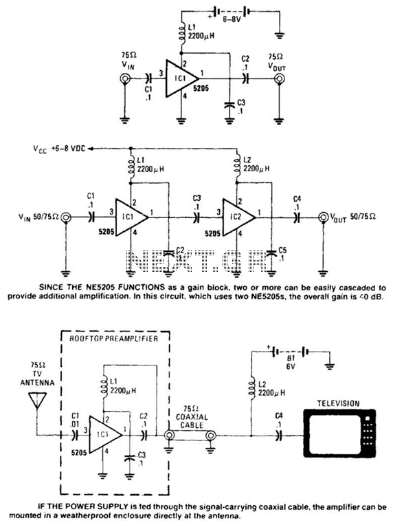
Except for the coupling and decoupling capacitors, IC1 is a complete wideband amplifier that has a fixed gain of 20 dB up to 450 MHz. No external compensation is required. Since the NE5205 functions as a gain block, two...
The objective of this design is to create a Combo amplifier that was popular during the 1960s and 1970s. It is particularly effective as a guitar amplifier but can also perform well with various electronic musical instruments or microphones....