
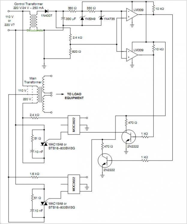
Automatic Ac Line Voltage Selector
The application note focuses on the integration of a PSoC device for the control of a BLDC motor, which is particularly suited for automotive wiper systems due to its efficiency and reliability. The use of LIN Bus 2.0 allows for a seamless communication interface between the motor controller and other automotive systems, ensuring that wiper operations can be effectively managed in response to various conditions.
The PSoC architecture provides flexibility in programming and configuring various peripherals, which is essential for tailoring the motor control algorithms to specific automotive requirements. The implementation details include the configuration of the PWM (Pulse Width Modulation) signals necessary for driving the BLDC motor, along with feedback mechanisms to monitor motor performance and adjust control signals accordingly.
Moreover, the application note elaborates on the LIN Bus 2.0 protocol, detailing how it facilitates robust communication between the motor controller and the vehicle's central control unit. This ensures that the wiper system can respond to inputs such as rain sensors or driver commands, enhancing overall functionality and safety.
The associated part families, CY8C27443 and CY8C29466, are highlighted for their suitability for this application, offering integrated features that streamline the design process. These components come with built-in support for the required communication protocols and motor control functionalities, making them ideal for automotive applications where reliability and performance are paramount.
Overall, this application note serves as a valuable resource for engineers looking to implement a BLDC wiper motor control system using PSoC technology, providing the necessary information to replicate and customize the design effectively.Abstract This Application Note describes PSoC device implementation of a BLDC (Brushless DC) windscreen wiper Motor Controller for automotive applications. LIN Bus 2. 0 is implemented to provide an Interface for controlling wiper operation. This Application Note sufficiently describes the technical details so that the user is familiar with the impo
rtant aspects of the design and is able to recreate the design specific to their exact requirements. This note also describes LIN Bus 2. 0 implementation in detail. Associated Part Family: CY8C27443 and CY8C29466 🔗 External reference
Related Circuits
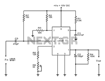
Converter circuits are commonly utilized in various applications, and there are several types available. A simple frequency-to-voltage converter circuit uses the IC LM331, which is essentially a precision voltage-to-frequency converter. This IC has numerous applications, and in this instance,...
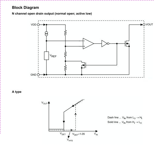
The HT70XX series comprises a collection of three-terminal low-power voltage detectors constructed using CMOS technology. Each voltage detector within the series is designed to detect a specific fixed voltage within the range of 2.2V to 7V. These detectors feature...
A voltage-controlled oscillator (VCO) is an oscillator whose frequency is regulated by a voltage signal. The VCO discussed here can generate both triangular and square wave outputs. The control voltage can be adjusted between 5 mV and 5 V,...
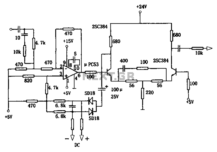
The circuit is designed for a broadband linear detection application with a bandwidth of 10 MHz. It serves as a millivoltmeter measuring instrument suitable for frequencies exceeding 10 MHz. The circuit features a linear detector utilizing operational amplifiers, specifically...
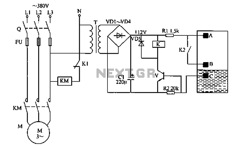
The liquid level automatic controller circuit consists of a power circuit, a level detection circuit, and a control implementation circuit. The power circuit is formed by a power transformer T, rectifier diodes YD1 to VD4, and a filter capacitor...
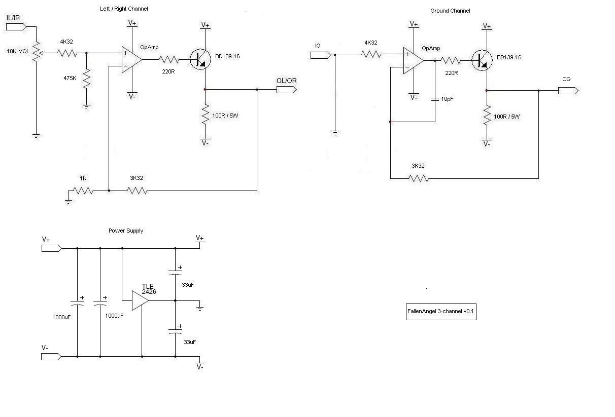
The schematic shows R4 at the emitter of the transistor, as suggested by Amb and Majkel. It should be positioned between the operational amplifier and the transistor, which is also the correct configuration in the CanAmp. The amplifier observed...
Warning: include(partials/cookie-banner.php): Failed to open stream: Permission denied in /var/www/html/nextgr/view-circuit.php on line 713
Warning: include(): Failed opening 'partials/cookie-banner.php' for inclusion (include_path='.:/usr/share/php') in /var/www/html/nextgr/view-circuit.php on line 713