
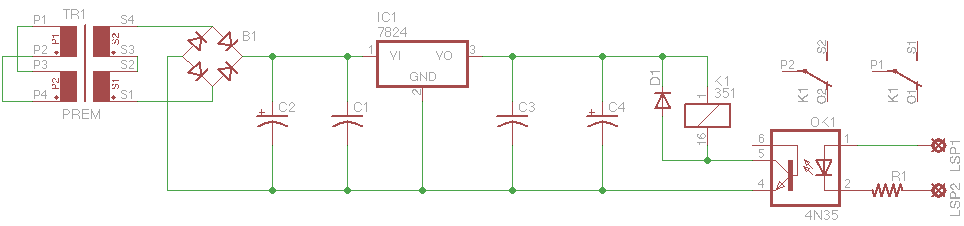
Automatic level control circuit
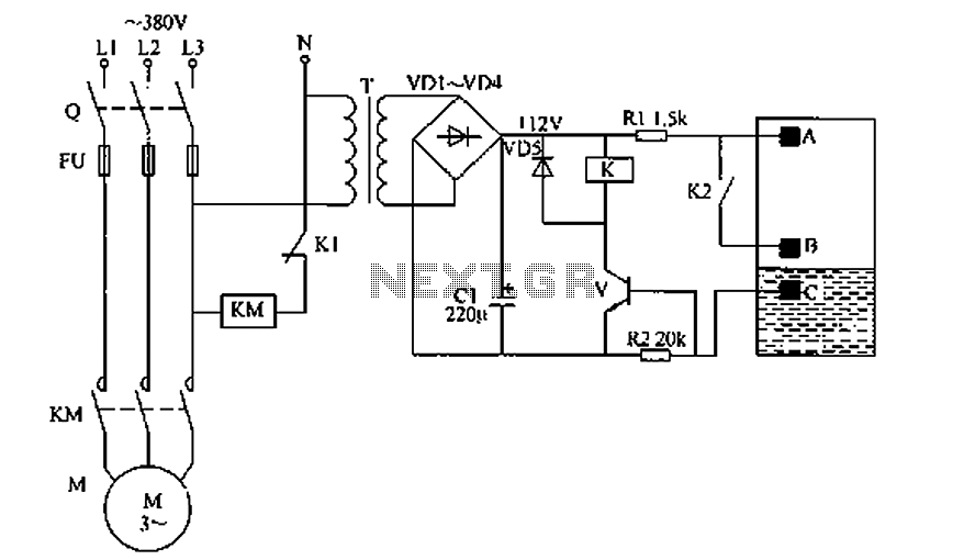
When there is no liquid or the liquid level is below the low-level electrode B, the base potential of control transistor V is equal to the emitter potential, causing it to turn off. Consequently, relay K does not activate, and its normally open contact K2 remains off while the normally closed contact K1 is turned on, allowing the AC contactor KM to energize the pump motor M and initiate the dosing pump operation. When the liquid level reaches the high-level electrode A, a +12V voltage is applied through resistor R1, allowing current to flow through the resistance of the liquid to the main electrode C, thus turning on transistor V partially. This energizes relay K, which disconnects normally closed contact K1 and connects normally open contact K2, resulting in the AC contactor KM turning off and cutting power to the pump motor M, thereby stopping the dosing pump. As the liquid level drops to the low-level electrode B or below, the potential at the base of transistor V returns to match the emitter potential, turning it off and releasing relay K. This reactivates normally closed contact K1 and deactivates normally open contact K2, allowing the AC contactor KM to energize the pump motor M again, thus resuming the dosing process. This cycle continues, providing unattended automatic hydraulic control. If a single pump is used, the AC contactor KM is not necessary, and the pump can be connected directly to the AC motor contactor coil.
For component selection, resistors R1 and R2 should be 1/4W carbon film types. The capacitor C should be a 16V aluminum electrolytic type. Diodes VD1 to VD5 can be 1N4001 or 1N4007 silicon rectifier types. Transistor V should be a 3DG12 or C8050 silicon NPN type with a current gain greater than 25. Relay K should be a 12V DC type, while AC contactor KM should have a coil voltage of 220V AC. The transformer T should be rated between 3 to 5W for 12V output.
This circuit design effectively automates the control of liquid levels in tanks or reservoirs, ensuring efficient operation of pumps and dosing systems while minimizing the need for manual intervention. The selection of robust components ensures reliability and longevity of the system in various operational conditions.Circuit works The liquid level automatic controller circuit from the power circuit, a level detection circuit and control the implementation of circuit, as shown in FIG. FIG automatic level control circuit Power circuit from the power transformer T, rectifier diode YD1 ~ VD4 and filter capacitor C form. Liquid level detection circuit by the high level electrode A, B low level electrode and the main electrode C components.
Executed by the control circuit of the relay K, the control transistor V AC contactor KM and other components. AC 220V voltage by T Buck VD1 ~ VD4 rectifier and C filter to produce 12V DC voltage supply control execution circuit.
When no liquid or liquid pool level is below the low level electrode B, V control tube base potential of the emitter due to the same electric potential and is off, the relay K is not action, its normally open contact K2 off, normally closed contact K1 is turned on, the AC contactor KM pull power, so that the rate pump motor M power operation, plus begin dosing pump. When the liquid level reaches the high level electrode tanks at A, + 12V voltage through a resistor R1, a high level electrode A, conductive resistance of the liquid and the main electrode C was added to the base V, so that V n partial conduction relay K energized work, disconnect the normally closed contact K1, K2 normally open contact connected, AC contactor KM off, the contact is released, plus cutting power pump motor M, plus dosing pump stops.
When the reservoir pool level drops to a low level electrode B or less, V and the base potential prisoners and emit the same electric potential and off, the relay K release, its normally open contact K2 off, normally closed contact K1 access pass, the AC contactor KM pull, plus pump motor M is energized, re-start dosing. Again and again, unattended automatic hydraulic control. If the pump using a single sum, you can not have AC contactor KM. Adding directly to the single pump and connected to the AC motor contactor coil ends can be. Component selection R1 and R2 are selected 1 / 4W carbon film resistors. C selected voltage is 16V aluminum electrolytic capacitors. VD1 ~ VD5 are selected 1N4001 or 1N4007 type silicon rectifier diodes. V selects 3DG12 or Model C8050 silicon NPN transistor, which requires current amplification factor greater than 25.
K small selection of 12V DC relay. KM choose coil voltage is 220V AC contactor. T optional 3 ~ 5W of 12V power transformer.
Related Circuits
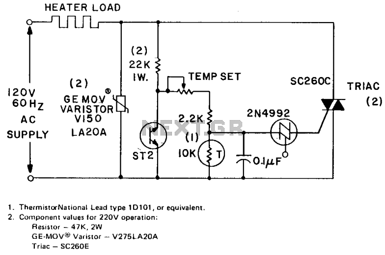
The circuit can control up to 6 kW of heating with moderate gain using a 25-amp triac (SC260D). Feedback is provided by a negative temperature coefficient (NTC) thermistor, which is positioned near the environment being temperature controlled. The temperature...
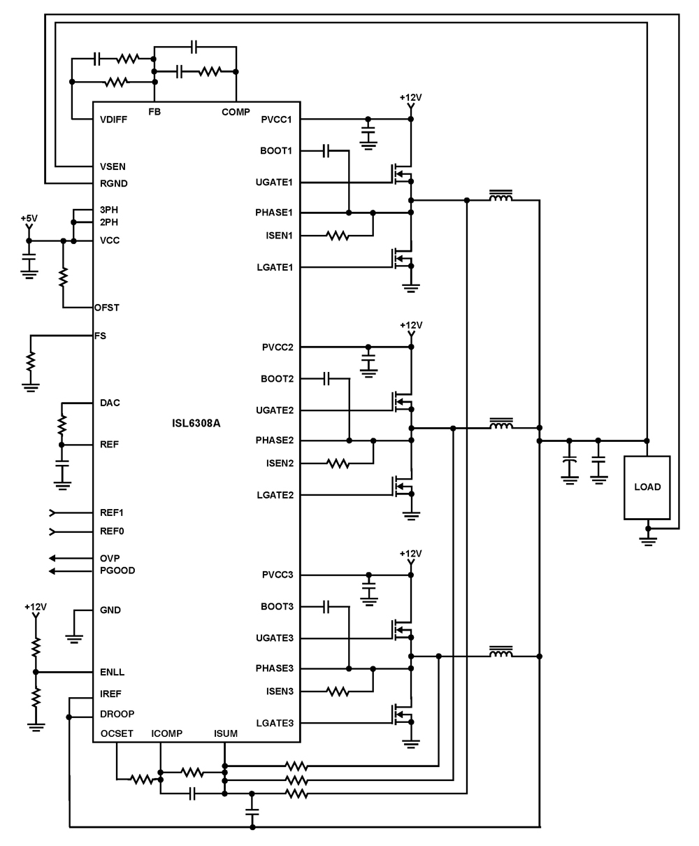
The ISL6308A is a three-phase PWM control integrated circuit (IC) equipped with built-in MOSFET drivers. It delivers precise voltage regulation suitable for various applications, including high current low voltage point-of-load converters, embedded systems, and other general low voltage medium...
The high input impedance, high slew rate, and high voltage characteristics of the CA3140 operational amplifier make it suitable for use in a Wien-bridge sine wave oscillator. The basic circuit configuration for the Wien-bridge sine wave oscillator is depicted...
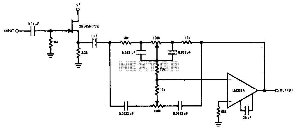
The 2N5458 JFET offers high input impedance and low noise characteristics, making it suitable for buffering an operational amplifier feedback tone control circuit. The 2N5458 is a Junction Field Effect Transistor (JFET) known for its superior electrical characteristics, particularly in...
This is a common control voltage in industrial and telecommunications equipment, making relays frequently found in surplus equipment. Many relays can operate effectively on both AC and DC, providing a straightforward solution when the control voltage is switched mechanically,...
Nowadays, an increasing number of audio-visual devices in homes are interconnected. This is particularly true for televisions, which may be linked to DVD players. In modern home entertainment systems, the integration of various audio-visual devices enhances user experience and convenience....
Warning: include(partials/cookie-banner.php): Failed to open stream: Permission denied in /var/www/html/nextgr/view-circuit.php on line 713
Warning: include(): Failed opening 'partials/cookie-banner.php' for inclusion (include_path='.:/usr/share/php') in /var/www/html/nextgr/view-circuit.php on line 713