
Automatic contrast meter
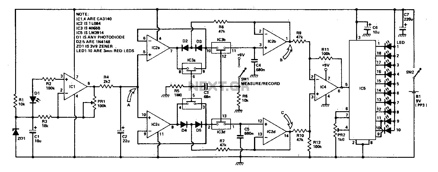
The described circuit employs a photo-amplifier, which is essential for transforming the light intensity variations from an enlarger into a corresponding voltage signal. This voltage is then directed to two peak detectors, each designed to track specific voltage extremes: one for the highest (positive) peak and the other for the lowest (negative) peak. The use of capacitors in conjunction with these peak detectors serves a dual purpose. Not only do they store the detected voltage peaks, but they also contribute to the functionality of sample and hold circuits, which are crucial for capturing and maintaining the peak values during the measurement phase.
Upon completion of the measurement, the sample and hold circuits are activated to retain the stored voltages. The outputs from these circuits provide the maximum and minimum values of the light intensity, which are essential for further processing. The differential amplifier then takes these two outputs and computes their ratio, thereby providing a relative measure of the light intensity variations. This computed ratio is crucial for applications where precise light intensity control is required.
Finally, the result of the differential amplifier's computation is presented visually through an LED bargraph meter. This display method allows for immediate and intuitive interpretation of the light intensity levels, making it a practical solution for users who need to monitor light conditions in real-time. Overall, this circuit arrangement effectively integrates light sensing, voltage processing, and user-friendly output visualization, making it suitable for various applications in photography and optical measurements.The circuit arrangement consists of a photo-amplifier which feeds a voltage derived from varying light levels in an enlarger to a pair of peak detectors. One follows the peak positive voltage and the other the peak negative voltage. The capacitors used for storing the voltage peaks in the followers also form part of sample and hold circuits which are then switched to hold after the measurement.
Their outputs represent the maximum and minimum values of light intensity A differential amplifier then computes the ratio of these values, and the result is displayed on an LED bargraph meter. 🔗 External reference
Related Circuits
This circuit resembles the "Fading Red Eyes" circuit found in the LED section, designed to fade a pair of red LEDs. In this iteration, the lamps are dimmed by adjusting the duty cycle, allowing for the use of higher...
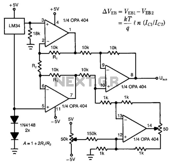
The LM34 is utilized as a sensor in the design of this linear thermometer. Its output represents the difference between two base-emitter voltages (Veb) of two transistors that operate at different collector-current densities. These current densities are denoted as...
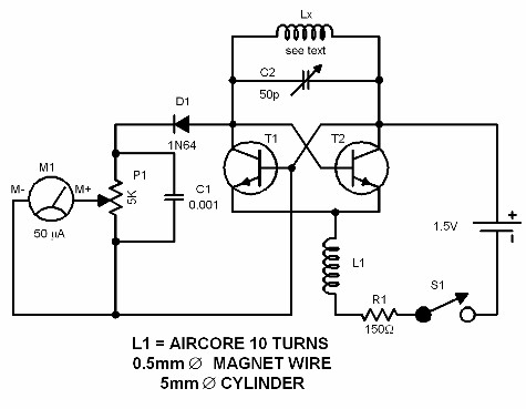
A dip meter operates by measuring the resonance of an LC circuit. The circuit presented is designed for use in the VHF range. The tester coil is connected to the LX terminals and positioned near the LC circuit under...
The proximity detector detects the movement of PC board pieces as the wheel rotates, generating an output signal with a clear transition between high and low voltage levels, making it suitable for triggering counting or processing circuits. Following this...
This simple and easy to make circuit is a 5 LED VU Meter based on LB1409 IC from SANYO, which will indicates the volume level of the audio signal it senses. SUPPLY 12V DC @ 50mA. PR1 REF SET....
To explain in a little more detail, using the ATMEGA8's internal 2.5 volt band gap reference means that by using a resistive divider ahead of the A-to-D converter, the input could be scaled such that any voltage range from...