
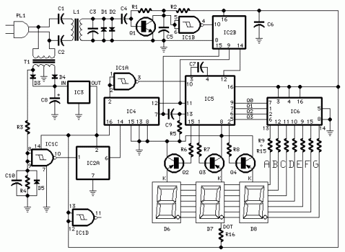
LED Digital Panel Meter

The circuit utilizes the ATmega8 microcontroller, which features an integrated 10-bit Analog-to-Digital Converter (ADC) capable of handling a voltage range from 0 to 2.5 volts, achieved through a resistive divider network. This divider allows for scaling of higher voltage inputs, such as the specified 102.3 volts, down to the ADC input range. The design incorporates a bandgap reference voltage of 2.5 volts to ensure consistent performance across varying conditions.
In order to accommodate the higher voltage range, resistors R2, R3, and R4 are employed to create a voltage divider that reduces the input voltage to the ADC. The switching of these resistors is controlled by PORTB bit 0, which toggles between high impedance (input mode) and low output mode. This configuration allows for seamless integration of the resistive divider into the circuit while maintaining control over the ADC input.
Power regulation is handled by a LM78L05 voltage regulator, which provides a stable 5V output from a higher voltage source, such as 9V or 30V. The choice of TO-92 or TO-220 packages for the regulator depends on the maximum input voltage and thermal considerations. The circuit has been designed to ensure that the maximum power dissipation does not exceed safe limits, taking into account the thermal resistance of the regulator.
Decoupling capacitors and inductors are strategically placed on the analog VCC line to stabilize the voltage and reduce noise. A 0.1 μF capacitor is implemented at the ADC input to maintain low impedance and act as a low-pass filter, minimizing noise that could affect the ADC readings.
The resistors used in the voltage divider are precision resistors with low temperature coefficients to ensure accuracy in the voltage scaling. While metal film resistors are preferred, carbon film resistors can also be utilized with acceptable results, provided they are selected to match the desired divider ratios.
Overall, the circuit is compact and efficient, making it suitable for applications requiring precise voltage measurements within the specified range. The design emphasizes good practices in component selection and layout to enhance reliability and performance. To explain in a little more detail, using the ATMEGA8's internal 2.5 volt band gap reference means that by using a resistive divider ahead of the A-to-D converter, the input could be scaled such that any voltage range from 0 to 2.5 volts or higher could be accommodated. If the range had less than 1024 steps, then some resolution would be lost. For Don's application, a 102.3 volt scale would be necessary. The least significant digit would be 100 millivolts. And when he used the meter to measure (for example) 10.0 volts, the 100 millivolt resolution would be a little bit coarse.
The circuit came out to be very simple and compact. The ATMEGA8 is the lowest pin count AVR controller that I could find that has an onboard 10 bit A-to-D converter. It had no problem directly driving the four digits delivering an average approximately 50 milliamps to the display.
The on-chip clock oscillator also saved some parts. I am not sure whether the 8 uH inductor and 0.33 uF decoupling capacitor on the analog VCC was necessary, but I used them as a good practice. Better to put a couple of extra parts on the board than to take the chance of having to take the board back and add them later.
The schematic above shows an ISP (In Circuit Programming) connector, which I had originally built onto the board so I could debug the firmware, using the crash-and-burn method - write the code and see if it runs. After I was satisfied with the performance of the meter, I cut off the portion of the board that had the ISP connector on it.
Power for the chip is regulated with a 7805 regulator. In this particular case, I used a TO-92 LM78L05 regulator. Measuring the current into the 5 volt input, I find a maximum of about 56 milliamps current drain, when displaying 08.88 volts. When powered from a 9 volt power source, the dissipation of the LM78L05 will be 224 mW. With a 200 degrees C per watt thermal resistance, junction temperature should be about 45 degrees above ambient.
A little more calculation showed that the maximum safe input voltage to the LM78L05 is just a little above 12 volts if my maximum ambient temperature is 40 degrees C. In Don's case, where he would power the meter from 30 volts, it would be best to use a TO-220 version of the LM7805.
When in the 102.3 volt range, some additional resistors, R2, R3, and R4, are connected to ground, so the input divider reduces 102.3 volts to 2.5 volts (40:1). These additional parts are switched in and out of the circuit by switching PORTB bit 0 I/O pin between being an input with no pullup to a low output.
I have noticed that with some AVR controllers, one cannot switch the mode of the output pin directly between these two states, so be sure to consult individual data sheets if you try this on other controllers. Notably, on the ATTINY861, it took a little bit more "bit twiddling" to switch an I/O pin between high impedance and low impedance states.
The 0.1 uf capacitor from the input of the A-to-D converter is there to not only keep the impedance seen by the input from being too high, but also to act, in conjunction with the input resistors, a low pass filter to reduce noise on the input. The fixed resistors in the divider are 1%, 50 ppm/C metal film resistors that I bought at a literal fire sale in Bangkok.
I realize that not everybody has these exact values on hand. But don't worry. Carbon film resistors should work about as well, though you might see the calibration drift a little with temperature. Just pick carbon film values that are close to the vales of the resistors shown in the schematic, and it should work fine.
You have the divider ratios, so if you feel the need, you can work out the optimum component values. 🔗 External reference
Related Circuits
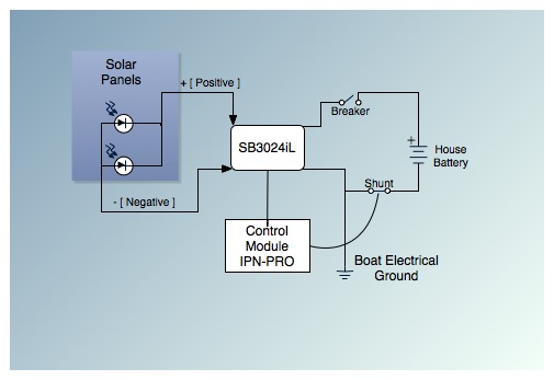
This is the fifth post in a five-part series on saving between $5,000 and $9,000 by installing a cockpit arch and a pair of solar panels on an Allied Princess ketch rigged sailboat named Aletheia. The series will continue...
This circuit is designed for precise centigrade temperature measurement. It features a transmitter section that converts the sensor's output voltage, which is proportional to the measured temperature, into frequency. The output frequency bursts are transmitted through the mains supply...
Many amateur receivers are equipped with an S meter that does not operate logarithmically. The proposed circuit is intended to enhance such receivers. Although integrated circuits like the CA3089 or CA3189 are not commonly used today, they play a...
The sphygmomanometer can be categorized into two main types: the mercury sphygmomanometer and the electronic sphygmomanometer. The mercury sphygmomanometer is known for its accuracy, but it requires professional operation and is prone to observational errors due to subjectivity. Additionally,...
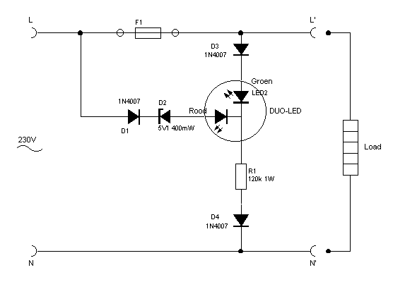
This indicator shows through a dual-LED see if a fuse is intact. The module is designed for 230 V AC. The green LED illuminates when the fuse is still good, the red lights when the fuse is broken. Perhaps...
This circuit is a digital voltmeter with an LED display, ideal for measuring the output voltage of a DC power supply. It features a 3.5-digit LED display with a negative voltage indicator and measures DC voltages from 0 to...