
Automatic Retransmitting Makeshift Repeater

This circuit is designed to facilitate the operation of a simple audio-derived repeater using two handheld radios, where one radio functions as the receiver (Radio 1) and the other as the transmitter (Radio 2). The operation hinges on the ability of Radio 2 to transmit when its microphone input is shorted with a resistance of 1-2 kΩ, which is critical for compatibility with the circuit.
The core of the circuit employs a MOSFET, specifically the BS108, which is chosen for its low gate-source (G-S) threshold voltage. This allows for efficient operation with minimal audio signal levels. The circuit is powered by the audio signal itself, making it self-sufficient and eliminating the need for an external power source.
When Radio 1 receives a signal, it opens its squelch circuit, allowing audio to flow. A small portion of this audio signal is diverted to the gate of the MOSFET. The MOSFET then turns on, allowing current to flow from its drain to source, which effectively activates Radio 2. As long as the audio signal is present from Radio 1, the MOSFET remains in a conductive state, keeping Radio 2 transmitting the received audio.
Capacitor C1 plays a vital role in coupling the audio signal from Radio 1 to the gate of the MOSFET, ensuring that the control signal is clean and adequately filtered. The output of Radio 2, which is connected to the antenna, then broadcasts the audio received from Radio 1, effectively creating a makeshift repeater system.
This circuit is particularly useful for radio amateurs who may need to extend their communication range or for situations where direct line-of-sight communication is obstructed. By utilizing existing handheld radios, the repeater system can be set up with minimal cost and effort, making it an attractive solution for enhancing radio communication capabilities.This circuit will be of interest to the radio amateur and anyone posessing two radios, (one of which must be able to transmit i.e. a transceiver). It is a self powered (audio derived) repeater circuit for receiving a signal and re-transmitting it via the other radio.
This little circuit can turn two hand-held radios into a makeshift repeater. Any radio will work fine as Radio 1, but Radio 2 must be a Yaesu, or some other type that also goes on the air when its microphone input is shunted with 1-2 kiloohms. As soon as a radio signal opens Radio 1`s squelch circuit, a tiny amount of energy stolen from the audio signal turns on the MOSFET and it conducts as long as the audio is present.
While it conducts, Radio 2 is on the air, retransmitting the content supplied by Radio 1 through C1 and P1. The BS108 has a conveniently low G-S threshold voltage. 🔗 External reference
Related Circuits
The battery charger circuit is designed to charge 6V 4.5 AH lead-acid batteries. The schematic is straightforward and utilizes only a few components. The IC LM317T serves as the core component of the circuit. It features an automatic charging...

This automatic light dimmer circuit enables controlled lighting that gradually turns on or off. The operation is as follows: when switch S1 is closed, capacitor C1 charges slowly. Once the voltage across C1 reaches 0.6 volts, transistor T1 begins...
The charging circuit automatically stops when the battery is fully charged, allowing the emergency light to remain connected to the AC mains overnight without concern. The circuit consists of two main sections: the inverter and the charger. The inverter...
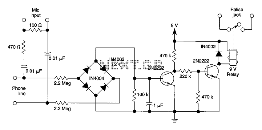
The DC voltage present on the telephone line typically ranges from 45 to 50V when on-hook and drops to approximately 6V when off-hook. This condition activates a step-down circuit relay, which in turn controls a tape recorder. Audio input...
Voltage regulator ICs from the 78xx series deliver a stable output voltage in contrast to a highly variable input supply, provided that the common terminal is grounded. Any voltage applied above zero volts (ground) to the common terminal is...
When mains power is absent, relay RL2 remains in a de-energized state, supplying battery power to the inverter section through its normally closed contacts and switch S1. The inverter section consists of IC2 (NE555), configured in astable mode to...