
Automatic Lamp Dimmer Circuit

This automatic light dimmer circuit employs a combination of passive and active components to achieve a gradual transition in lighting intensity. The primary components include a switch (S1), a capacitor (C1), a transistor (T1), a light-emitting diode (LED), a light-dependent resistor (LDR), a silicon-controlled rectifier (SCR), and a potentiometer (P2).
Upon closure of switch S1, capacitor C1 begins to charge through a resistor, which dictates the charging time constant. The gradual increase in voltage across C1 is critical, as it determines when T1 will start conducting. The threshold voltage of 0.6 volts is a characteristic of the transistor, allowing it to enter the active region and drive the LED.
The brightness of the LED is directly proportional to the current flowing through T1, which is regulated by the voltage across C1. As the LDR detects ambient light levels, its resistance decreases when the LED is illuminated, thereby influencing the SCR's conduction. This feedback loop creates a smooth increase in brightness as the circuit responds to the changing conditions.
When S1 is opened, the discharge path for C1 through T1 is slow, allowing for a gradual reduction in current, thus dimming the LED smoothly. This feature is essential in applications where abrupt changes in lighting can be undesirable, such as in home theater systems or ambient lighting setups.
The adjustment of potentiometer P2 is crucial for setting the desired anode voltage of diode D1. This voltage adjustment ensures that the circuit remains in a stable state during standby, preventing any flickering or unintended activation of the lighting system when it is not in use. The design of this circuit exemplifies the integration of electronic components to achieve a user-friendly and aesthetically pleasing lighting solution.This automatic light dimmer circuit makes it possible to control a lighting system so that it turns on or off slowly. The circuit works this way: when switch S1 is closed, the capacitor C1 is slowly charged. Once the voltage at C1 reaches 0. 6, transistor T1 begins to conduct and the LED also begins to light. If the capacitor voltage increases furt her, then transistor T1 conducts more current and in return the LED lights brighter. If the LED lights up, the LDR resistance decreases causing the SCR to conduct periodically earlier. This tehnique causes the lighting system to turn on slowly. On the other hand if switch S1 is turned off, meaning the switch is opened, the LED does not immediately turn off since the capacitor voltage at the base of T1 discharges slowly. The LED slowly dims until finally turns off. This causes the lighting dim out before it finally turns off. Potentiometer P2 must be set so that the anode voltage of D1 is about 0. 7 volts. If this is done, the capacitor voltage will be around 0. 5 volts during standby, meaning lights off. 🔗 External reference
Related Circuits
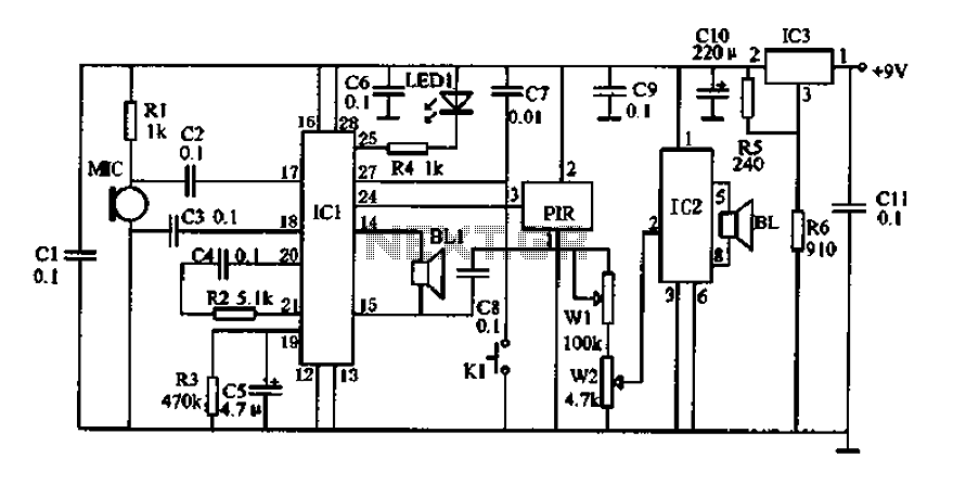
Doppler effect sensor N1 (RD627), operational amplifier N2 (LM358), and a special integrated circuit for imitating dog barking (N3, KD5608) are utilized along with other components. When there is no activity detected in the monitoring area by N1, the...
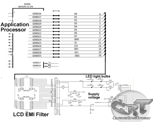
An LCD (liquid crystal display) is an electronically modulated optical device composed of multiple pixels filled with liquid crystals, arranged in front of a light source (backlight) or reflector to generate images in either color or monochrome. The block...
The danger always exists when fuel gases such as propane or natural gas are confined to a small area. The toxic gas alarm utilizes a tin-oxide semiconductor. A coil of thin wire is heated by a 12 V battery...
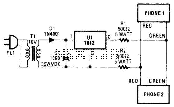
Two telephones can be used as an intercom by utilizing this circuit. Older style rotary phones that are non-electronic may be the most suitable for this application. Additionally, handsets alone can be powered in this manner. This intercom circuit allows...
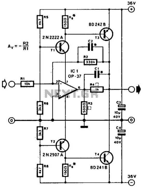
This line driver is capable of driving low-impedance lines with a maximum output of 70 V peak-to-peak. IC1 functions as a low-noise operational amplifier suitable for operation at 15 V. T1 and T2 serve as voltage regulators for the...
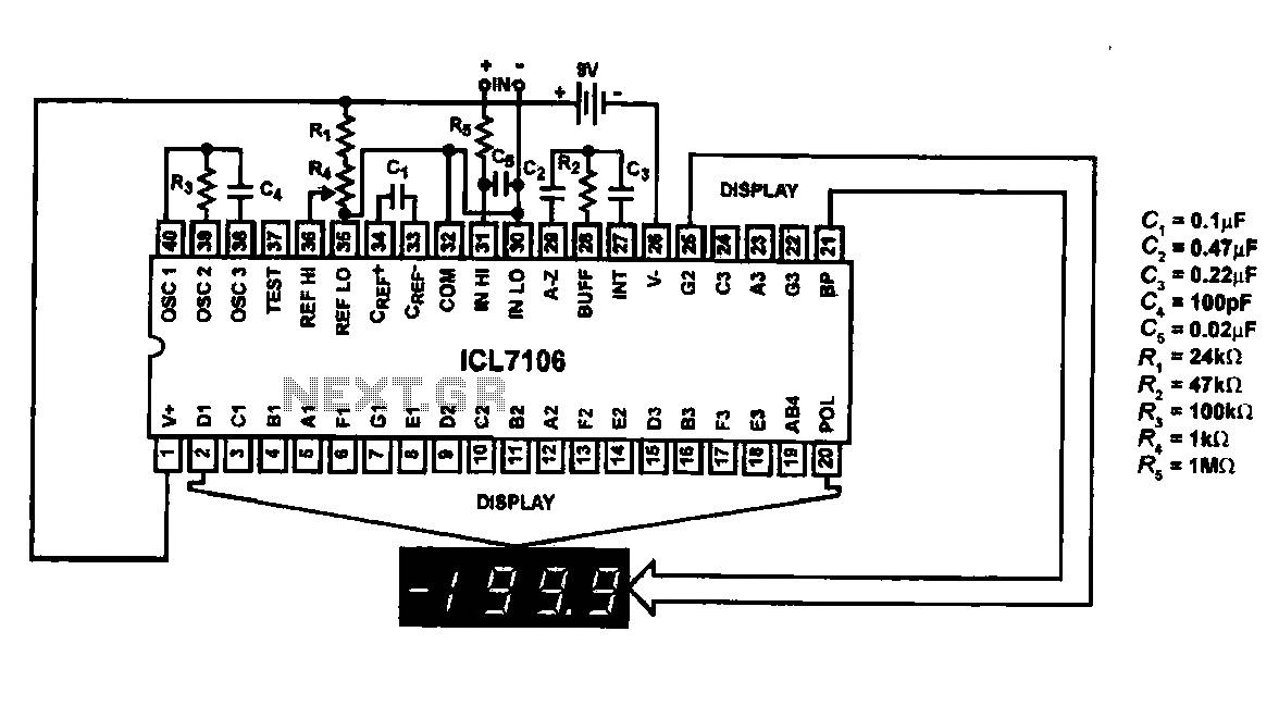
This circuit utilizes the ICL7106 / ICL7107 chip to drive a liquid crystal display (LCD). In this configuration, the ICL7106 / ICL7107 functions as a signal measurement and analog-to-digital (A/D) converter. It detects an analog input signal, amplifies it,...