
Automatic ttl morse-code keyer
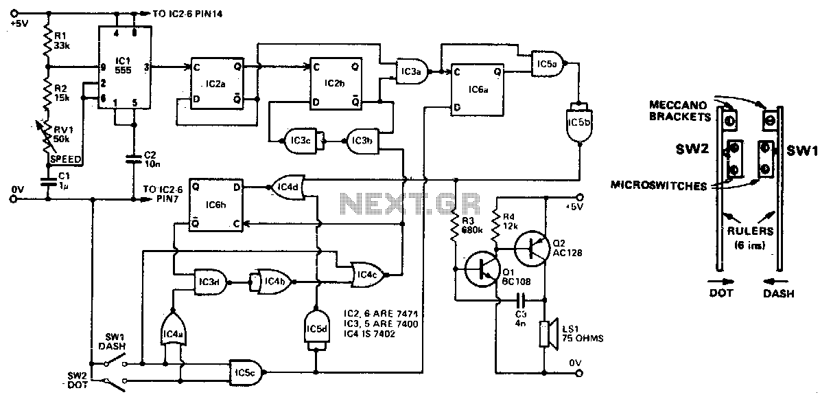
The described circuit is designed to generate Morse code signals, represented as "dits" (short signals) and "dahs" (long signals), at adjustable speeds ranging from 11 to 39 words per minute (wpm). The speed of the generated signals can be modified by adjusting the resistance of resistor R2. By decreasing the resistance value of R2, the circuit can achieve a higher transmission speed, thus allowing for more rapid generation of Morse code.
The keying mechanism is facilitated by two switches, SW1 and SW2, which can be implemented as a homebrew paddle key. This type of key allows the operator to manually control the generation of dits and dahs by pressing one switch for a short signal and another for a long signal. The paddle design provides a user-friendly interface for Morse code transmission, enabling efficient and precise operation.
In a typical schematic, the circuit may include additional components such as capacitors for signal smoothing, diodes for protection against reverse polarity, and possibly a microcontroller to manage timing and signal generation. The output can be connected to an audio oscillator or a radio transmitter, enabling the Morse code signals to be transmitted over radio frequencies or converted to audible tones.
Overall, this circuit presents a versatile solution for generating Morse code, suitable for both hobbyists and professionals interested in amateur radio and communication technologies.Automatically generated dits and dahs are produced over a speed range of 11 to 39 wpm. The upper limit can be raised by decreasing R2 SWl and SW2 can be a "homebrew" paddle operated key. 🔗 External reference
Related Circuits
It was designed for use on a The London Model Railroad Group's large O scale layout located at London, Ontario, Canada. The prime requirements for the club throttles were that they be rugged, reliable and produce as little heat...
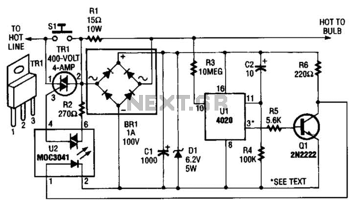
The automatic porch-light control circuit maintains a triac in an active state until a 4020 divider counts a series of 60-Hz power line pulses. This circuit is designed to turn off the light after a specified duration, utilizing pins...
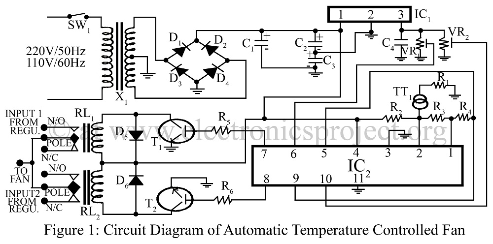
An automatic temperature-controlled fan regulates the fan speed based on temperature variations using the temperature transducer AD590 and an op-amp LM324 circuit diagram. The automatic temperature-controlled fan circuit utilizes the AD590 temperature transducer, which provides an output voltage that is...
Power supplies designed for use with TTL logic circuitry must protect against over-voltage, which can rapidly damage TTL chips. The duration of over-voltage that can harm TTL chips is too short to activate any conventional fuse, necessitating the use...
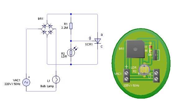
Adjust the value of R1 to achieve optimal performance of the LDR sensor. If, in practice, a resistance of 2.2 MΩ still activates the lamp, it is possible to increase the value of R1 to a larger resistance of...
This circuit is a simple air flow detector that signals the presence of air flow. The sensor utilized is a filament incandescent lamp. Components include an air flow detector, a sensor, an LED, and an LM339 operational amplifier. The air...
Warning: include(partials/cookie-banner.php): Failed to open stream: Permission denied in /var/www/html/nextgr/view-circuit.php on line 713
Warning: include(): Failed opening 'partials/cookie-banner.php' for inclusion (include_path='.:/usr/share/php') in /var/www/html/nextgr/view-circuit.php on line 713