
Automatic Temperature Controlled Fan
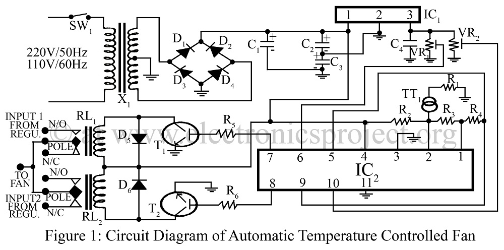
The automatic temperature-controlled fan circuit utilizes the AD590 temperature transducer, which provides an output voltage that is linearly proportional to the absolute temperature in Kelvin. This transducer is connected to the input of an operational amplifier (op-amp) LM324, which is configured to amplify the small voltage signal from the AD590. The op-amp serves as a comparator, comparing the output voltage from the temperature sensor with a reference voltage that corresponds to a predetermined temperature threshold.
When the temperature exceeds the set threshold, the op-amp output changes state, triggering a control mechanism that adjusts the fan speed. This can be achieved through a pulse-width modulation (PWM) signal or by controlling a transistor that regulates the power supplied to the fan. The speed of the fan increases with rising temperatures and decreases as the temperature falls, ensuring efficient cooling and energy consumption.
The circuit may also include additional components such as resistors to set the reference voltage, capacitors for stability, and diodes for protection against reverse polarity. Proper layout and grounding techniques should be employed to minimize noise and ensure reliable operation of the temperature control system. Overall, this schematic design provides an effective solution for maintaining desired temperature levels in various applications.Automatic Temperature Controlled Fan control the speed of fan according to change in temperature using temperature transducer AD590 and op-amp LM324 circuit diagram. 🔗 External reference
Related Circuits
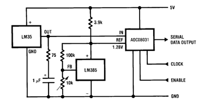
The circuit illustrates a Temperature to Digital Converter diagram utilizing the LM35 sensor, which includes a beneficial bypass capacitor connected from VIN to ground and a series RC damper. The described circuit employs the LM35 temperature sensor, a precision integrated...

This is a simple hobby circuit for a remote-controlled toy car. The primary component utilized is the IR sensor circuit, which includes a TSOP IR receiver. This receiver allows the user to start and stop the DC motor of...
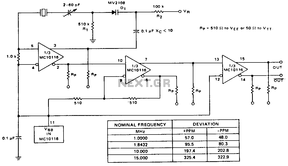
A voltage-variable capacitance tuning diode is connected in series with the crystal feedback path. Adjusting the voltage on the variable resistor (VR) changes the capacitance of the tuning diode, which in turn tunes the oscillator. The 510 kΩ resistor...
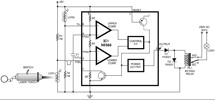
This circuit is designed around a 555 timer and utilizes a minimal number of components. Its simplicity allows even beginners to easily assemble and operate it as a control device. A readily available laser pointer can be used to...
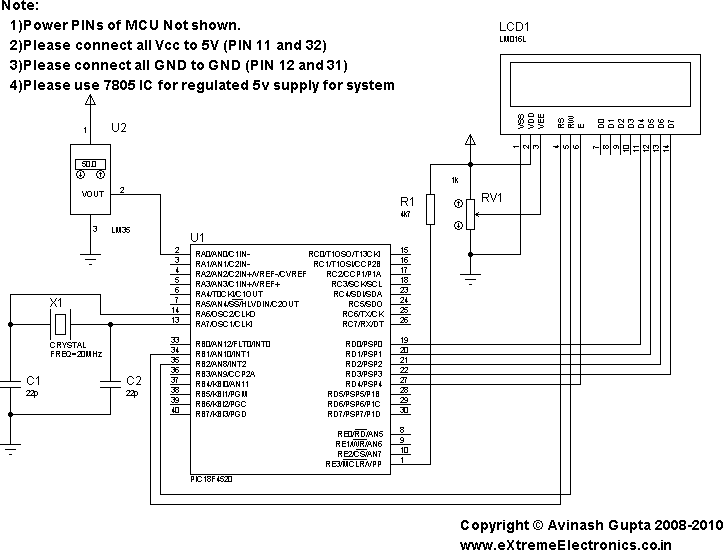
In the present day, a wide variety of sensors are available to measure almost anything. This tutorial will explore the fascinating world of sensors, starting with a very simple analog temperature sensor, the LM35. The process of interfacing it...
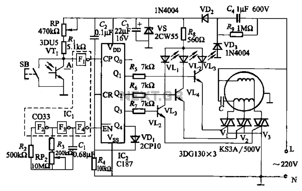
The circuit depicted in Figure 3-5 can be controlled manually using button SB or automatically via light detection using phototransistor VTj. When light from a flashlight is detected by phototransistor VTj, the fan will activate, adjusting its speed automatically...
Warning: include(partials/cookie-banner.php): Failed to open stream: Permission denied in /var/www/html/nextgr/view-circuit.php on line 713
Warning: include(): Failed opening 'partials/cookie-banner.php' for inclusion (include_path='.:/usr/share/php') in /var/www/html/nextgr/view-circuit.php on line 713