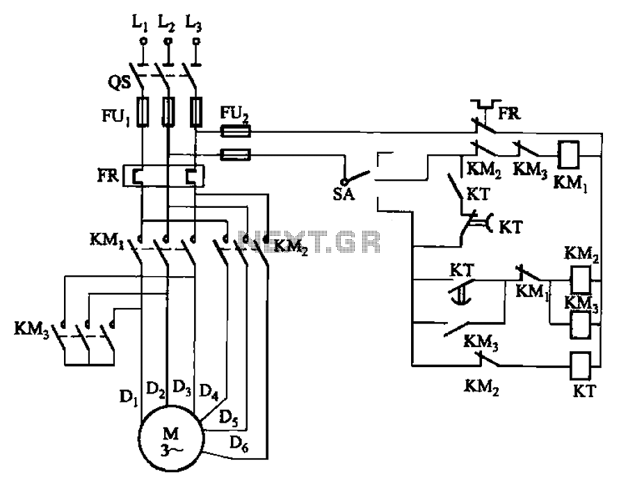
2 -Y- connection automatic three-speed motor acceleration control circuit
#motor control
#automatic acceleration
#contactor
#time relay
#three-speed motor
#speed transition
#starter circuit
#industrial control
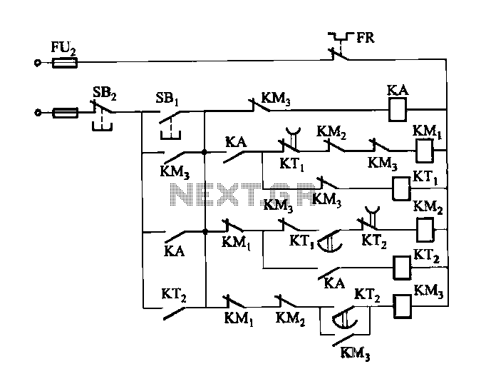
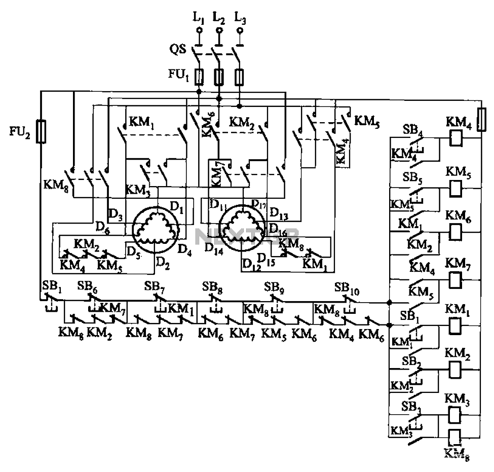
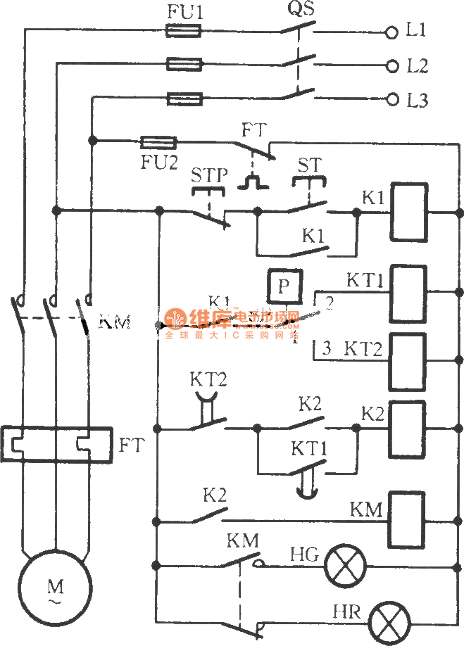
Description: Figure 3-118 illustrates an automatic acceleration control circuit. This circuit employs a male contactor time relay, enabling the motor to start automatically at a low speed before transitioning to high-speed operation.
The automatic acceleration control circuit depicted in Figure 3-118 is designed to enhance motor performance by providing a controlled ramp-up in speed. The primary component, a male contactor time relay, plays a crucial role in managing the motor's startup sequence. Upon activation, the time relay initiates the motor at a predetermined low speed, allowing for a gradual increase in speed to high operational levels.
The circuit typically consists of the following components: a power supply, the male contactor time relay, a motor, and various control elements such as switches and resistors. The power supply provides the necessary voltage and current to the motor and relay. The male contactor time relay is configured to close its contacts after a specific delay, which is adjustable based on the application requirements. This delay ensures that the motor does not start at full speed immediately, thus preventing mechanical stress and potential damage.
In operation, when the circuit is powered, the relay remains open for a set duration, during which the motor operates at low speed. After the elapsed time, the relay closes, allowing the motor to transition smoothly to high-speed operation. This method not only improves the reliability and longevity of the motor but also enhances overall system efficiency.
In addition to the relay, the circuit may incorporate safety features such as overload protection and thermal sensors to monitor motor temperature. These elements ensure that the motor operates within safe parameters, further contributing to its durability and performance. The design can be tailored to various motor types and applications, making it a versatile solution for automatic acceleration control in industrial and commercial settings.Figure 3-118 automatic acceleration control circuit. It uses the male contactor time relay, the motor starts automatically from a low speed by the speed the transition to high- speed operation.
