
2Y-2Y-2Y-connected three-speed motor contactor control circuit
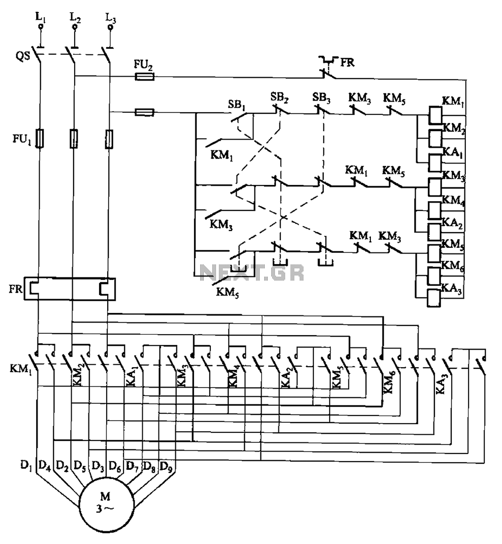
This circuit design incorporates a series of contactors that facilitate the control of motor speed in an efficient manner. The use of double buttons enables seamless transitions between different speed settings without interrupting the motor's operation.
The SBi button initiates high-speed operation, engaging a specific contactor that connects the motor to the full supply voltage, thereby maximizing its performance. The SBz button is intended for medium-speed operation, which typically involves a resistor in series with the motor to limit current and reduce speed effectively. Lastly, the SB3 button activates low-speed operation, likely utilizing a different configuration of resistors or contactors to achieve the desired lower speed setting.
The circuit is designed to enhance user experience by eliminating the need to stop the motor before changing speeds, which can improve productivity and reduce wear on mechanical components. The careful arrangement of the contactors ensures that the motor receives the appropriate voltage and current for each speed setting, while also providing necessary protection against overload conditions.
Overall, this circuit exemplifies a practical and efficient approach to motor speed control, utilizing simple yet effective components to achieve desired operational flexibility. Circuit shown in Figure 3-115. It uses contactors and double buttons, so when converting speed without press stop press ugly, can be directly converted. SBi, SBz button and SB3 are high, medium and low speed operation button.
Related Circuits
This compact water sensor alarm circuit emits a loud warning sound when a humidity sensor detects the presence of water. The circuit utilizes the low-power comparator LM1801 from National Semiconductor. A fixed reference voltage for the integrated circuit is...
This is a simple circuit designed for an audio amplifier project to control the speaker output relay. The purpose of this circuit is to manage the relay that activates the speaker output in the audio amplifier. The circuit is...
When the fan seized up in my source and I changed it to a type with much less noise, turned on my computer, the largest source of noise CPU cooler fan. The computer I have a boxed Pentium III...
A 1000 Watts audio power amplifier circuit designed for outdoor use. A circuit diagram is needed urgently to facilitate the construction of this high-power amplifier, which is a personal passion project. The design of a 1000 Watts audio power amplifier...
This audio noise filter circuit functions as a bandpass filter specifically designed for the audio frequency range. It effectively filters out unwanted signals that fall below or above the desired audio frequencies. The circuit comprises two filters: a low-pass...
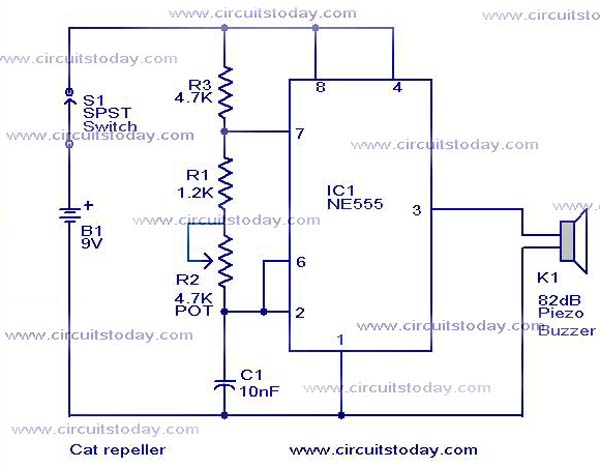
This cat and dog repeller circuit is designed to deter animals from specific areas. The circuit utilizes ultrasonic sound, which is known to provoke a strong response in many animals, particularly cats. The design features an astable multivibrator configuration...