
Variable Fan Controller
The described circuit involves a fan control system aimed at reducing noise levels while maintaining adequate cooling for a Pentium III processor. The circuit utilizes an NTC thermistor as a temperature sensor, which provides feedback for controlling the fan speed based on the CPU temperature. The primary components include a MOSFET (T1) for switching the fan on and off, a trimmer potentiometer (P) for setting the temperature threshold, and additional transistors (T2 and T3) for managing the fan's operation.
The NTC thermistor is critical for temperature sensing, as its resistance decreases with increasing temperature, allowing for a precise control mechanism. The trimmer potentiometer is used to adjust the sensitivity of the temperature control, enabling the user to set a specific temperature at which the fan will activate. The MOSFET is used to handle the current required by the fan, ensuring efficient operation without generating excessive heat.
The circuit design necessitates that the fan is properly grounded to ensure accurate speed detection, as many modern fans incorporate a tachometer signal that reports back to the motherboard. The design is simplified to include only essential components, making it cost-effective and straightforward for implementation in a PC environment.
The lack of a protection circuit is a notable design choice, as it may lead to potential risks if the fan were to stop unexpectedly due to a fault in the circuit. In such cases, the current flow will cease, and the system will rely on the backup transistor (T3) to maintain power to the fan, albeit not in a controlled manner.
The overall layout of the components is crucial for optimal performance and reliability. Proper soldering techniques must be employed when connecting flexible contacts to ensure a robust connection that can withstand repeated use within the confines of a computer case.
For practical implementation, the circuit can be tested using a laboratory power supply, and adjustments can be made using software utilities like Speedfan, which can monitor CPU temperatures and simulate load conditions to evaluate the performance of the fan control system. The specified resistor values and component types (e.g., SMD resistors, specific transistor models) must be adhered to for the circuit to function correctly within the designed parameters.
In summary, this fan control circuit represents a practical solution for managing CPU cooling while minimizing noise, suitable for retrofitting into older computer systems or for use in custom builds where noise reduction is a priority.When the fan seized up in my source and I changed it to a type with much less noise, turned on my computer, the largest source of noise CPU cooler fan. The computer I have a boxed Pentium III processor in slot 1, which is practically dismountable and fan replacement would be difficult.
"Boxing" is a type of fan with ball bearings and replacement of the type of plain bearing to reduce noise, while cooling, but not reliability. Another option was to reduce the fan speed. I tried the program Speedfan. This enabled to set the fan speed, but I was unable to convince him to regulate the speed according to CPU temperature.
The PSU I have the controller in [1] , which I witnessed in earlier computers. I wanted to use it for the CPU fan, I used to but your friend "discovered" the regulator is used in battery charger for model. Involvement of the regulator in Figure 1 is ingeniously simple. The whole controller has only three components: sensors - NTC Thermistor, Trimmer for temperature control and MOSFET.
The transistor is the best "standard" type with a threshold voltage around 4 V. For use in PC controller had to be adjusted. It should be that the fan is grounded, otherwise it does not capture special fan outlet "rotation". For proper function of the controller under quite simply figure A transistor to produce the opposite type of conductivity and change the polarity and the fan. The resulting involvement of the figure 2 is not accompanied by a protection circuit. The thermistor is connected to the controller a short cable. The frequent handling inside the PC could happen that turn leads somewhere. The regulator according to Figure 1 , the fan has stopped rotating, which could have fatal consequences especially for AMD.
The regulator according to Figure 2 , in which case the current flow stops and the thermistor trimmer, transistor T2 is closed and the transistor T3 is connected in parallel to T1, opens. The fan is powered by the almost full supply voltage. The opening of T2 requires very little current, the transistor is open and current, passing through the thermistor at 40 ° C.
The recovery is only in the trimmer and the overall control function. The controller can revive "the table" when powered from a laboratory source, the more I worked this way but only to check the function and set the slider to the PC. The program Speedfan or another utility to leave the screen listing the CPU temperature and run a program that loaded the CPU to 100%.
Suitable programs are for DOS or Windows 3.1, or compression schemes for audio or video. Starting and stopping the program can be CPU heat as needed. Trimmer, then set the temperature at which the fan spins. The difference between the temperature at which the fan is still standing, and the temperature at which rotates the "content" is only a few ° C. In my computer I set the regulator at 38 ° C. This temperature might be too low. Component placement is to figure 5 . MOSFET and trimmer are equipped with the "component side" transistors T2, T3 and resistor from the circuit.
K2 connector for connecting a standard ventilator, his counterpart, who need to connect to the MB, is sold only in the "cable" design. The flexible contacts must be soldered pieces of thicker wire (see Figure 6 ), for which the solder plug into the controller board.
When soldering is necessary to ensure that the tin was only in places where it is pressed with pliers crimp the cable and the flexible nezatekl contacts. R1 10 kOhm, SMD1206 P 5 kOhm, Trimmer PT6V (PT6H) C1 In 1947 ?F/16 T1 IRFD9120 T2 BC858C SMD T3 BC807-40 SMD NTC 10 kOhm thermistor ZD Zener diode 5.6 V (If necessary / if Needed ) connectors "lock up" PSH02-03W PFH02-03P PCB bcs39
🔗 External reference
Related Circuits
This PWM controller circuit is suitable for managing small motors with a maximum current consumption of 2A. For higher currents, additional cooling is required. The PWM (Pulse Width Modulation) controller circuit is designed to efficiently control the speed of small...
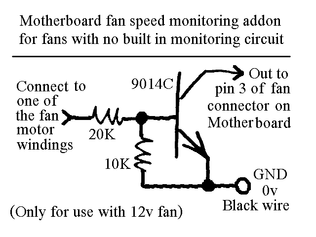
You will find this identical circuit inside most 3 wire computer fans with speed monitoring output to the motherboard. Peel off the sticker from the fan hub in order to access a motor winding pin for connecting up the...
The AC Motor Speed Controller is designed to regulate the speed of AC motors with carbon brushes, applicable to devices such as drills, saws, and vacuum cleaners. The AC Motor Speed Controller operates by adjusting the voltage and current supplied...
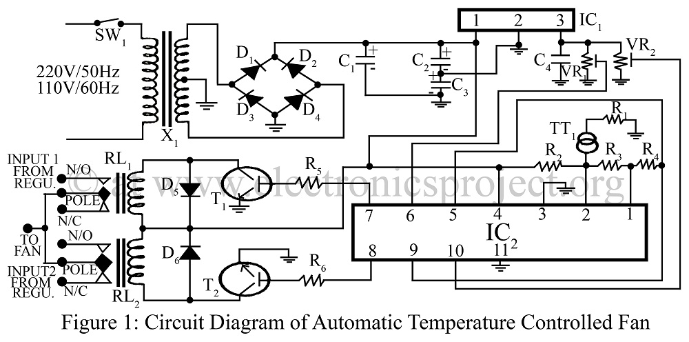
An automatic temperature-controlled fan regulates the fan speed based on temperature variations using the temperature transducer AD590 and an op-amp LM324 circuit diagram. The automatic temperature-controlled fan circuit utilizes the AD590 temperature transducer, which provides an output voltage that is...
Constantly changing light and sound analog controller circuit 05 The circuit described is an analog controller designed to modulate light and sound in a dynamic manner. This type of circuit typically employs a combination of resistors, capacitors, and operational amplifiers...
A Variable DC Power Supply is an essential tool for electronics hobbyists. This circuit is not entirely new, but it is simple, reliable, robust, and short-proof, offering variable voltage up to 24V and variable current limiting up to 2A....