
Automobile Interior Lights Fader
The automobile interior lights fader circuit is an essential enhancement for older vehicles, providing a more modern aesthetic and functionality to the interior lighting system. The circuit operates by controlling the voltage applied to the interior lights, allowing for a smooth transition between bright and dim states.
The LM324 operational amplifier serves as the primary element, configured in a way that enables it to function as a variable resistor. This configuration allows for the gradual increase and decrease of current flowing to the lights, resulting in a fading effect.
The circuit typically includes additional components such as resistors, capacitors, and possibly a potentiometer, which can be adjusted to set the rate of fading. The resistors determine the current flow, while the capacitors are responsible for creating a time delay, thus controlling the fading speed.
To implement this circuit, it is essential to ensure proper power supply connections and to select components that can handle the voltage and current requirements of the vehicle's interior lighting. The circuit can be installed in conjunction with the vehicle's existing lighting system, allowing for seamless integration without significant modifications.
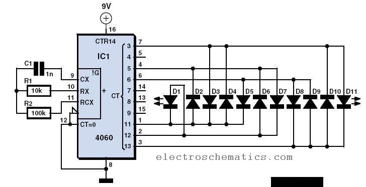
In summary, this fader circuit not only adds a sophisticated touch to the vehicle's interior lighting but also enhances user experience by providing a gradual transition in light intensity, making it a valuable upgrade for older automotive models.Automobile Interior Lights Fader Circuit diagram Circuit This circuit is similar to the fading eyes circuit above and is used to slowly brighten and fade interior lights of older cars. The circuit is based around the LM324 low p.. 🔗 External reference
Related Circuits

All that remains now is for the code to be compiled and converted to a HEX file that the PIC can understand. This is achieved easily with the PIC compiler that comes with the PICBASIC package. The PIC is...
This simple and inexpensive circuit built around a popular CMOS hex inverter IC CD4069UB offers four sequential switching outputs that may be used to control 200 LEDs (50 LEDs per channel), driven directly from mains supply. Input supply of...
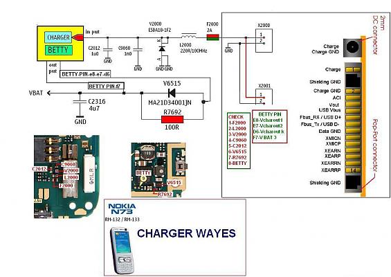
The display lights issue on the Nokia N73 can arise from various factors, such as a broken path in the display circuit or damage to the display driver, among others. This mobile repair guide offers pictures related to the...
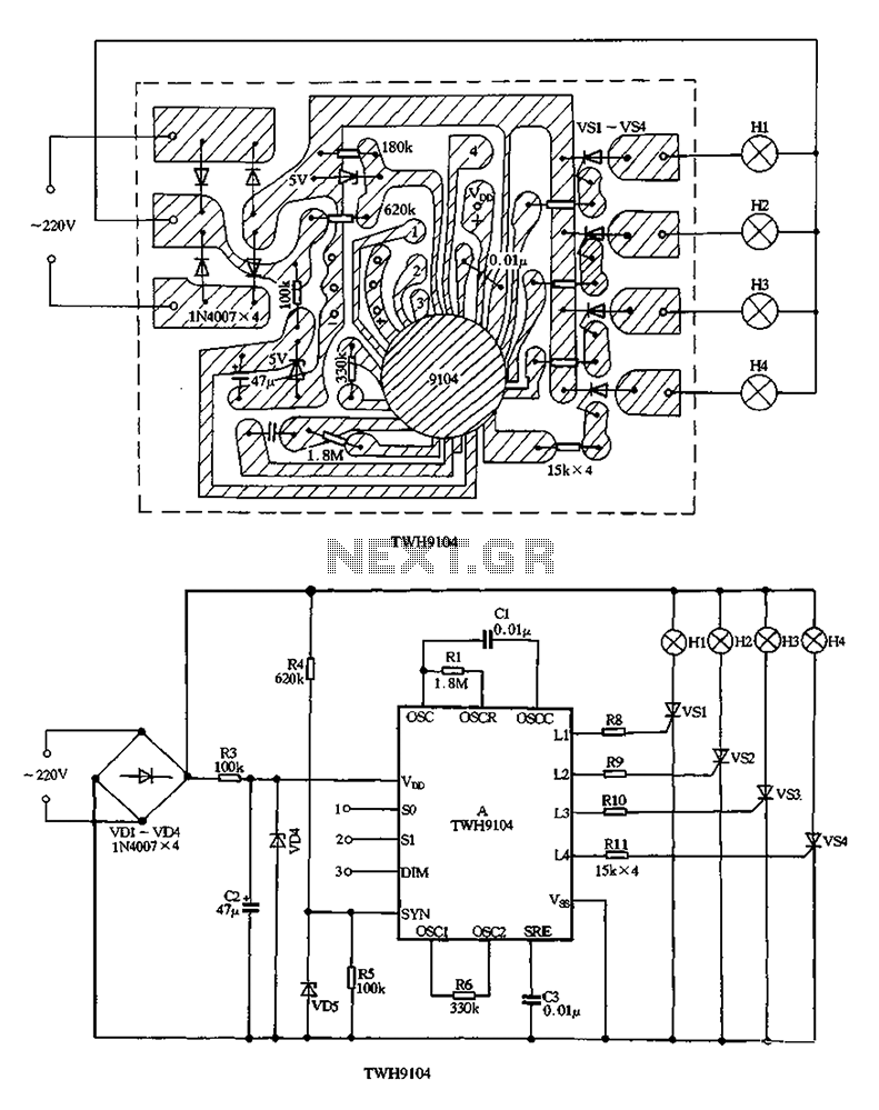
The circuit utilizes a VDI-VD4 bridge rectifier to convert 220V AC into a full-wave pulsating voltage, which powers lights H1 to H4. A buck regulator, composed of resistor R3 and diode VD4, reduces this voltage to approximately 5V DC,...
Have you already set up a Christmas tree in your house and decorated it with traditional lights? Build a couple of these LED lights to enhance the Christmas atmosphere. The project involves creating LED lights that can be used to...
Without a dedicated buck converter or white LED driver IC, it is possible to safely drive multiple standard high-efficiency white LED modules using available battery power. To design a circuit capable of driving high-efficiency white LED modules without a dedicated...
Warning: include(partials/cookie-banner.php): Failed to open stream: Permission denied in /var/www/html/nextgr/view-circuit.php on line 713
Warning: include(): Failed opening 'partials/cookie-banner.php' for inclusion (include_path='.:/usr/share/php') in /var/www/html/nextgr/view-circuit.php on line 713