
TWH9104 holiday lights ASIC

The circuit operates by first converting the 220V AC input into a full-wave pulsating voltage using the VDI-VD4 bridge rectifier. This rectification process is essential for providing a stable DC voltage to power the subsequent components. The output from the rectifier is then processed by a buck regulator, which steps down the voltage to approximately 5V DC. This lower voltage is crucial for the operation of the manifold A, which distributes power to the connected lights and components.
The thyristor gate control, achieved through resistors R8 and RIl, allows for precise manipulation of the conduction angle. By adjusting this angle, the intensity and flashing behavior of lights H1 to H4 can be tailored to meet specific requirements. This feature is particularly useful in applications where dynamic lighting effects are desired.
The circuit also includes an oscillation control mechanism, where the external resistor R6 influences the dimming characteristics of the lights. The ability to modify the dimming rate provides flexibility in creating different lighting moods, which can be particularly advantageous in decorative or atmospheric lighting applications.
Additionally, the chase rate of the lantern string is determined by the combination of resistors Rl and Cl. The use of a potentiometer allows for real-time adjustments, enabling users to customize the speed at which the lights chase. This can enhance the visual appeal of the lighting setup, making it suitable for various events or decorative purposes.
The mood lighting functionality is further enhanced by the inclusion of switches SI and DIM. These switches allow users to select from different flashing levels, providing an easy interface for changing lighting effects. By connecting short wires to the designated chip pads, users can effortlessly switch between various configurations, enabling a wide range of creative lighting options.
In summary, this circuit design offers a versatile and adjustable lighting solution that can be tailored for various applications, combining efficient power conversion, dynamic control, and user-friendly interfaces to achieve desired lighting effects.220V AC by the VDI-VD4 bridge rectifier to produce a full-wave pulsating voltage electricity for lights H1 ~ H4, the other side by R3 and VD4 buck regulator, C2 filtered output of about 5v DC voltage used for the manifold A Electricity. Manifold four output terminals Ll-LA by R8-RIl added thyristor gate, in order to change their conduction angle, so that lights H1-H4 according to need flash. Changes in OSCI, external oscillation resistor R6 resistance OSC2 can change the rate of dimming lights string.
Lantern string chase rate by Rl and Cl decisions, such as the potentiometer Rl to 2.2Mo series again a 510k o fixed resistor, adjust the potentiometer can adjust lantern string chase rate. Mood lights flashing by so, SI and DIM end (ie 1-3 determine the level of end) level, according to their needs reader with a short wire to l on a chip, 2, 3 pads and + ,.
contact pads can also be used in three lx2 small switch so, Sl, DIM side between VDD, vss be cut change in the composition of many tricks lantern controller.
Related Circuits
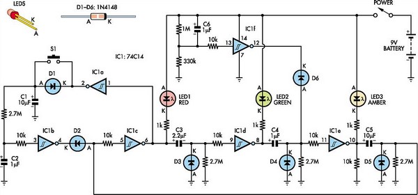
This toy traffic signal utilizes a single, cost-effective hex Schmitt-trigger inverter IC (IC1a-IC1f) to directly control three colored LEDs (red, green, and amber). Upon activation, the circuit illuminates the red signal for 30 seconds, followed by the green signal...
The silicon controlled rectifier (SCR), commonly referred to as a thyristor, functions similarly to a diode. When the cathode is negative relative to the anode, current can flow. The silicon controlled rectifier (SCR) is a semiconductor device that plays a...
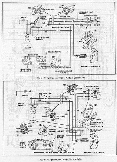
The system operates solely on vacuum. Upon inspection of the vacuum hoses, two brittle hoses were found that ran through the firewall to the headlight switch, where a slight hissing sound was noticeable when the lights were activated. Touching...
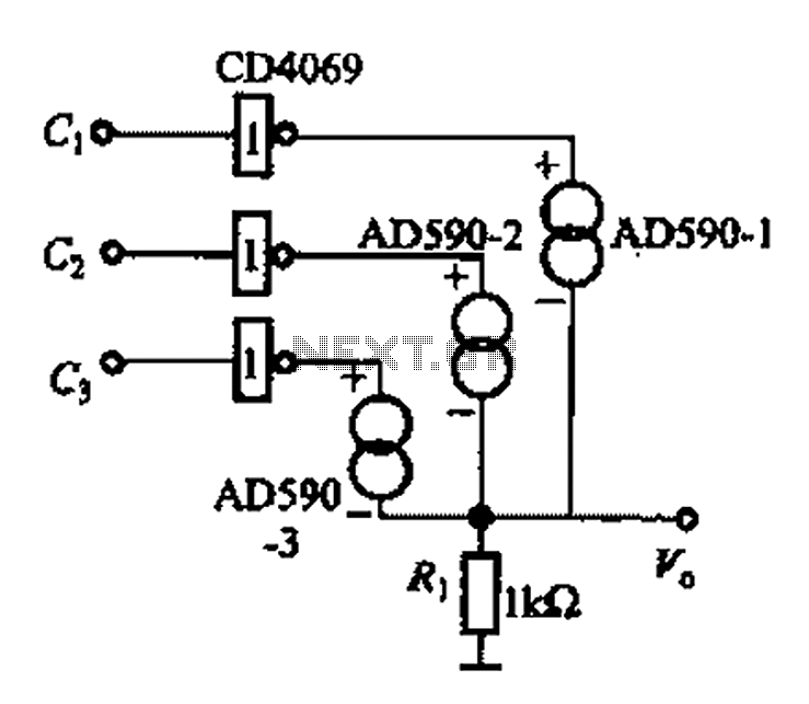
The AD590 is illustrated in a basic application circuit. As the AD590 provides a current output, a series resistance is used to convert this output current into a voltage. In the circuit, RP serves as the output voltage (vo)...
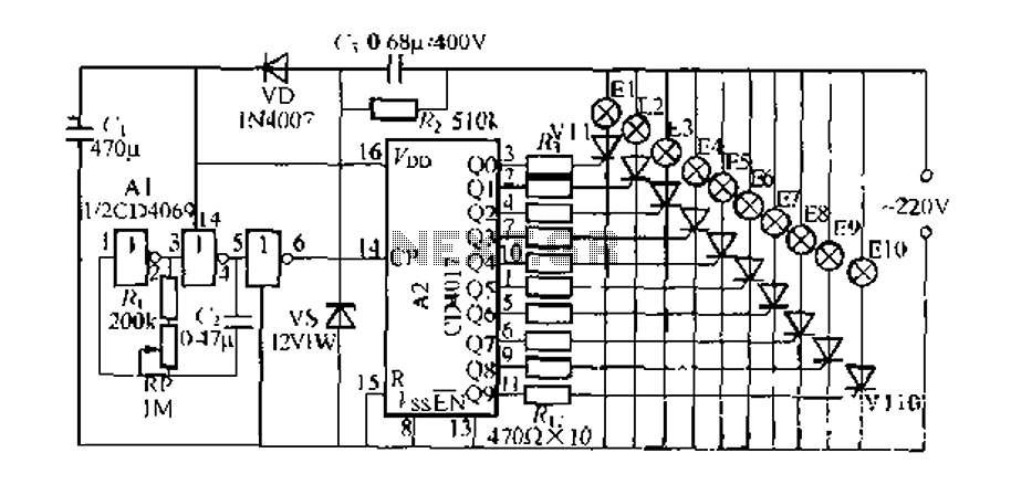
The digital integrated circuit consists of a controller for a string of ten road flashing lights, which drives the El-El0 string lights in a flashing cycle. The system utilizes a ten-count decoder, specifically the CD4017 digital integrated circuit. When...
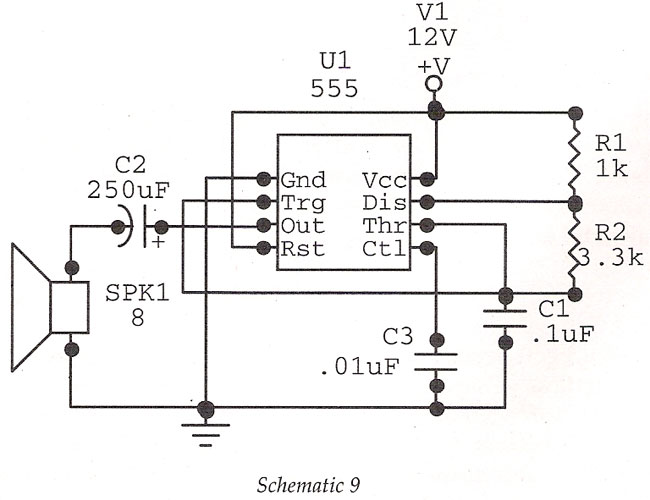
Basic Oscillator (Tone Generator) at 1.8 kHz using IC 555. This circuit features an astable oscillator configuration built around the 555 timer IC, generating an alarm tone of 1.8 kHz that directly drives a speaker. This is a fundamental...