
Automotive burglar alarm
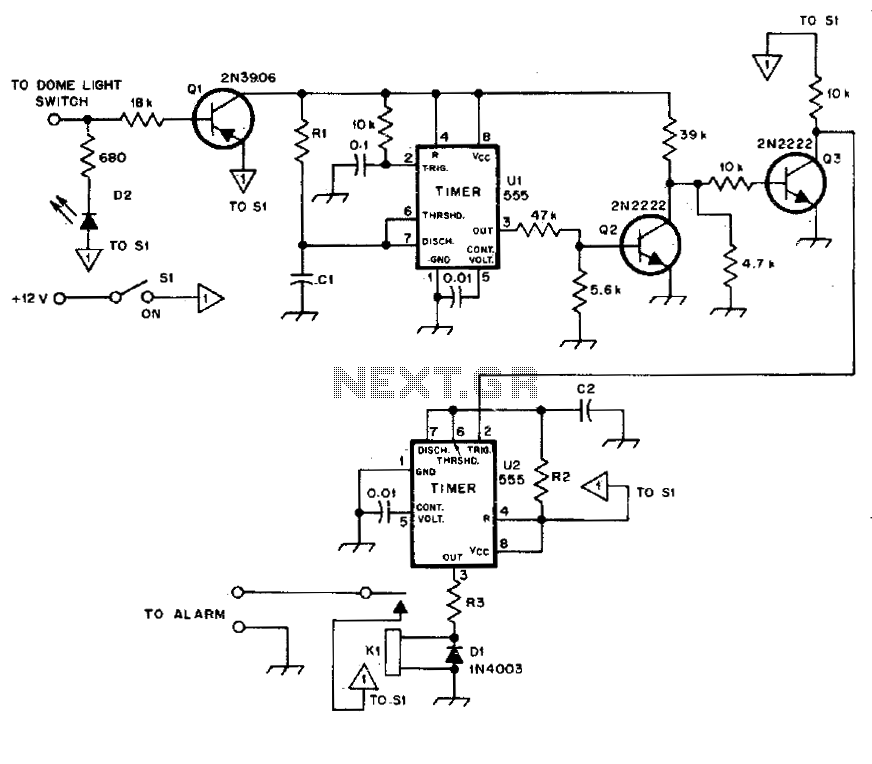
The described circuit functions as a delay-triggered alarm system, incorporating a timing mechanism and a manual reset feature. The core of the design involves a timer IC, such as the 555 timer in monostable mode, which is configured to initiate the alarm after a predetermined delay of 13 seconds.
Upon activation, the timer begins counting down from the set delay. Once the 13 seconds elapse, the output of the timer transitions to a high state, triggering the alarm circuitry. The alarm remains active for a duration that can be adjusted between 1 minute and 1.5 minutes, determined by the values of the timing resistors and capacitors in the circuit. After this period, the timer automatically resets, returning to its initial state and silencing the alarm.
An additional feature of the circuit is the manual reset capability. This is accomplished using switch SI, which, when opened and then closed, interrupts the power to the timer momentarily. This action forces the timer to reset, allowing for immediate deactivation of the alarm. The design ensures that the user can quickly silence the alarm without waiting for the automatic reset period to expire.
The overall schematic would typically include a power supply section, the timer IC, necessary passive components (resistors and capacitors for timing), the alarm output (such as a buzzer or LED indicator), and the manual reset switch SI. Proper consideration must be given to the component ratings and configurations to ensure reliable operation and safety.Alarm triggers on after a 13 second delay and stays on for 1-1 Vfe minutes. Then it resets automatically It can also be turned off and reset by opening and reclosing SI. 🔗 External reference
Related Circuits
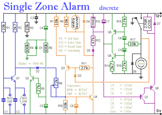
This is a single-zone alarm system featuring independently adjustable Exit, Entry, and Siren Cut-Off timers. It is designed to accommodate standard normally-closed input devices, such as magnetic reed contacts, foil tape, and passive infrared sensors (PIRs). The system can...
This circuit utilizing a 555 timer IC can be used as an alarm system to prevent the theft of your luggage, burglars breaking into your house, etc. The alarm goes ON when a thin wire, usually as thin as...
The Sun-Up Alarm can be used to provide an audible alarm for when the sun comes up or it can be used in a dark area and detect when a light comes on. It can also be used to...
The circuit includes automatic entry and exit delays, a timed bell cut-off, and a system reset feature. It accommodates both normally open and normally closed switches, making it compatible with common input devices such as pressure mats, magnetic reed...
The circuit utilizes the functions of reed switches to create a gate alarm powered by a universal AC/DC power supply oscillator. The circuit operates by integrating reed switches, which are sensitive to magnetic fields, into an alarm system designed to...
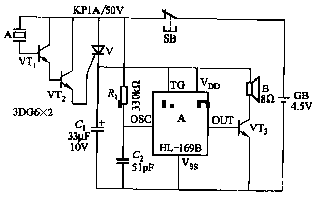
The circuit utilizes the HL-169B voice alarm integrated circuit (IC). It is designed for use in security applications, including glass doors, car doors, and windows, to act as a burglar alarm. When a thief applies force to these items,...
Warning: include(partials/cookie-banner.php): Failed to open stream: Permission denied in /var/www/html/nextgr/view-circuit.php on line 713
Warning: include(): Failed opening 'partials/cookie-banner.php' for inclusion (include_path='.:/usr/share/php') in /var/www/html/nextgr/view-circuit.php on line 713