
Battery Powered Burglar Alarm
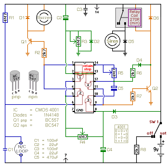
The single-zone alarm system operates based on a straightforward yet effective circuit design that utilizes a combination of resistors, capacitors, and a relay to manage the timing functions and control the output devices. The adjustable timers allow customization of the Exit, Entry, and Siren Cut-Off durations, providing flexibility based on user preferences and security needs.
The normally-closed input devices are connected to the circuit in such a way that any interruption in the loop will trigger the buzzer, alerting the user to potential security breaches. The choice of using a two-way switch (Sw1) simplifies the operation of the alarm, enabling easy arming and disarming.
The circuit's power supply section must be chosen carefully to ensure compatibility with the selected output devices. The relay serves as a critical component, allowing the system to control higher power outputs like sirens or buzzers without directly impacting the sensitive control circuitry.
The timers are implemented using resistors (R3, R4, R5) and capacitors, which define the delay periods. Users can experiment with different resistor values to achieve desired timing characteristics, making the system adaptable to various environments. For instance, using a higher resistance value will increase the delay time, while a lower value will shorten it.
The alarm's design also includes a feedback mechanism through the buzzer, which not only indicates the status of the system when arming or disarming but also serves as an alert if the alarm has been triggered during the user's absence. This feature enhances the overall security provided by the system.
In summary, the single-zone alarm system is a versatile and efficient solution for basic security needs, with adjustable settings and user-friendly operation, making it suitable for various applications in residential or light commercial environments. The accompanying documentation and prototype materials provide comprehensive guidance for assembly and troubleshooting, ensuring successful implementation of the alarm system.This is a single zone alarm - with independently adjustable Exit, Entry and Siren Cut-Off timers. It will accommodate the usual types of normally-closed input devices - such as magnetic-reed contacts, foil tape and PIRs. If you wish - you can use a mains power supply. But the extremely low standby current makes battery power a realistic option. I` ve used a 9-volt supply in the drawing - but the circuit will work at anything from 5 to 15-volts. All you need do is select a Siren, Buzzer, and Relay to suit the voltage you`re using. The alarm is easy to operate. Sw1 can be any type of two-way switch. If the Buzzer sounds when you switch the alarm on - the normally-closed loop is open. Switch off again - and check the building for open doors or windows. If the Buzzer does not sound - the loop is intact. Depending on the setting of R3 - you have up to about a minute to leave the building. As you do so - the Buzzer will sound. When you close the door behind you - it should stop sounding. This confirms that the loop has been restored within the time allowed. When you return and open the door - the Buzzer will sound. Depending on the setting of R4 - you have up to about a minute to switch the alarm off. If you fail to do so - the Siren will sound. Depending on the setting of R5 - the Siren will sound for up to about 20-minutes. Then it will switch off - and remain off. Of course - you can stop the noise at any time by moving Sw1 to the "off" position. For this type of device - really precise times are not necessary. If you like - you can replace the pots with fixed resistors. For example - 2M2 resistors should give you exit and entry delays of about 30-seconds - and a Siren cut-off time of about 10-minutes. After the cut-off timer has switched the Siren off - the Buzzer will continue to sound. So when you return - if the Buzzer is sounding - you`ll know that the alarm has been activated. The Support Material for this alarm includes a photograph of the prototype - a parts list - a detailed circuit description - a step-by-step guide to construction - and more.
🔗 External reference
Related Circuits
Schematic and description of a simple and easy-to-build NiCd and NiMH battery charger circuit that is capable of charging multiple NiCd and NiMH batteries. The circuit for the NiCd and NiMH battery charger is designed to be straightforward, allowing for...
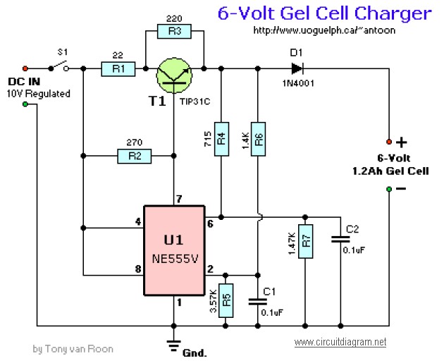
The following diagram illustrates the battery charger schematic for a 6V Gel Cell battery type. Component Parts List: R1 = 22 ohm, 1W; R2 = 270 ohm; R3 = 220 ohm; R4 = 715 ohm, 1%; R5 = 3.57K,...
The sensing circuit quickly disconnects the battery voltage and load when the voltage falls below a predetermined threshold. The one-way operation ensures that the circuit does not reconnect the load if the voltage subsequently rises above the threshold. Component...
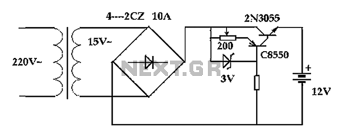
The circuit operates after a transformer, utilizing a bridge rectifier and conditioning for battery charging. The charging current transformer can be easily adjusted to provide approximately 12V at 100Ah battery charging. The required charging current is 10A, and a...
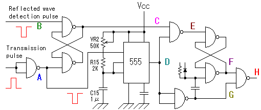
The alarm detector circuit operates differently from the Ultrasonic Alarm (1). In Ultrasonic Alarm (1), an alarm output is triggered by the detection of a reflected wave from an object during the setup time. Conversely, in this circuit, an...
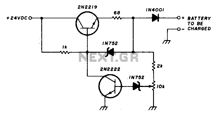
This circuit charges a battery at a rate of 75 mA, allowing the battery to remain in the charger indefinitely until fully charged. Once the battery reaches its full charge, the circuit reduces the current to a trickle rate....
Warning: include(partials/cookie-banner.php): Failed to open stream: Permission denied in /var/www/html/nextgr/view-circuit.php on line 713
Warning: include(): Failed opening 'partials/cookie-banner.php' for inclusion (include_path='.:/usr/share/php') in /var/www/html/nextgr/view-circuit.php on line 713