
AVANT Power Supply circuit
The Switched Mode Power Supply (SMPS) in the AVANT television operates on the principle of efficiently converting electrical power using high-frequency switching. The core component, a 32 kHz ramp oscillator, generates a square wave signal that drives the power supply's switching transistors. This process allows for the regulation of output voltage with minimal energy loss, making it suitable for compact electronic devices like televisions.
In the event of an overload, the protection circuit is designed to monitor the output and shut down the oscillator to prevent damage to the power supply and connected components. The absence of the 8-volt standby voltage indicates that the system is in a protective state, which prevents the standby light from illuminating.
To diagnose the issue effectively, it is crucial to differentiate between a genuine failure of the power supply and a fault elsewhere in the television that triggers the overload protection. The recommended approach involves measuring the voltage at the power supply board's connector P46. This connector is critical as it links the power supply to the rest of the television circuitry. By checking the voltage across pins 1 and 2 of P46, one can ascertain whether the power supply is functioning correctly or if the overload protection has been activated due to an internal fault.
Precautionary measures should be taken during this testing to ensure safety and prevent further damage. It is advisable to use insulated tools and, if necessary, to have a qualified technician perform the checks to avoid electrical hazards.The AVANT uses a Switched Mode Power Supply which means the heart of it is a 32khz ramp oscillator which is stopped if the overload protection circuit detects an overload. Without the oscillator running the 8 volt Standby voltage is not generated and is why your red standby light is not on.
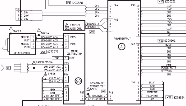
We first need to establish if the situation is because of an actual power supply failure or an overload somewhere in the TV which is shutting down the power supply through the overload protection. This is best done at the connectors on the power supply board and below is a block diagram showing the connectors involved.
Check the power at P46 between pins 1 & 2, be very careful 🔗 External reference
Related Circuits
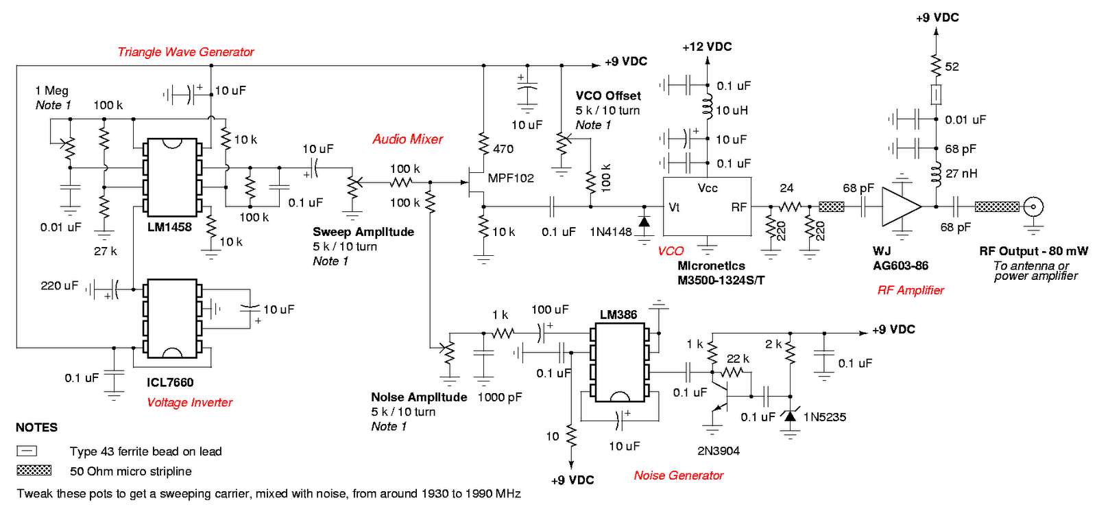
An admirable DIY GSM jammer or cellular mobile phone jammer schematic diagram designed for use with GSM1900, operating within the frequency range of 1930 MHz to 1990 MHz. The GSM1900 cellular mobile phone system is utilized in the USA,...
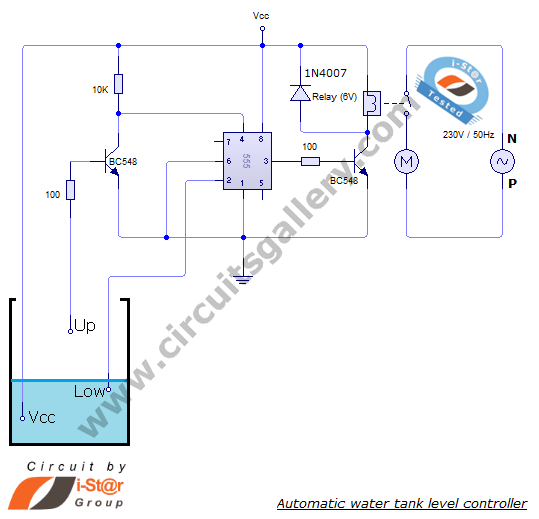
The automatic water level controller circuit is a straightforward engineering project that can automatically switch a domestic water pump on and off based on the water level in a tank. This motor driver circuit can be implemented at home...
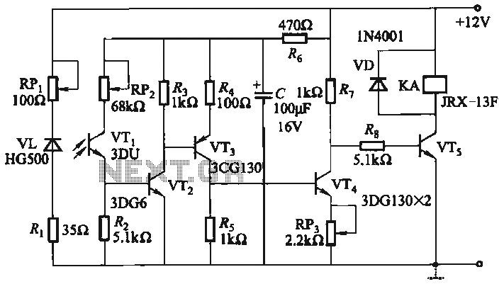
The infrared alarm system utilizes an infrared LED that emits invisible light. When this light is obstructed by an object, it triggers an alarm. The system comprises an infrared light-emitting circuit and a receiving circuit. The light-emitting diode (LED)...
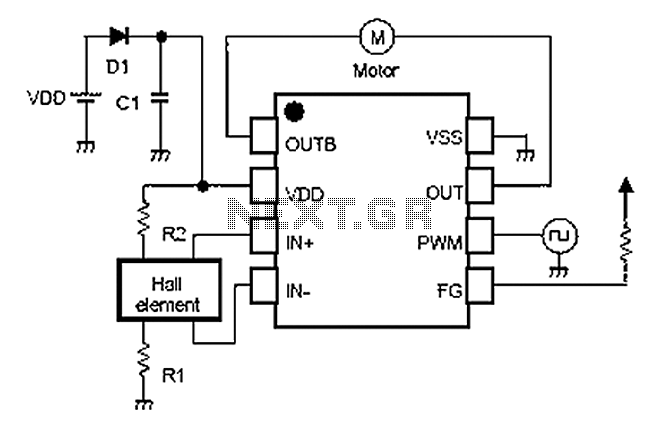
A simple single-phase brushless DC motor drive using the NJU7365 motor driver IC from New Japan Radio Co., Ltd. The NJU7365 is designed for single-phase motor applications and features built-in MOSFET motor drives, direct PWM input, FG output, and...
This circuit is a simplified version of a commercial uninterruptible power supply (UPS). It provides a constant regulated output of 5 volts and an unregulated supply of 12 volts. The described circuit functions as a basic uninterruptible power supply, designed...
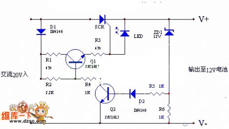
The circuit utilizes the positive half-cycle of an alternating current (AC) to charge a battery. It offers a rapid charging speed and has the potential to extend battery life. This charger is commonly used with standard motorcycles, demonstrating excellent...