
Basic Ups Power Supply

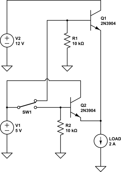
The described circuit functions as a basic uninterruptible power supply, designed to deliver two distinct voltage outputs: a regulated 5-volt output suitable for powering low-voltage electronic devices and an unregulated 12-volt supply that can be utilized for higher voltage applications.
The circuit typically incorporates a transformer, which steps down the mains AC voltage to a lower AC voltage suitable for rectification. Following the transformer, a bridge rectifier converts the AC voltage to pulsating DC. The 5-volt output is achieved through the use of a voltage regulator, such as the 7805, which ensures that variations in input voltage do not affect the output voltage, maintaining a steady 5 volts.
For the 12-volt output, the circuit usually employs a secondary winding on the transformer or a separate rectification path, providing a higher voltage that is not regulated, meaning it can fluctuate based on the load and input conditions. This output is often used to power devices that can tolerate voltage variations.
Additional components may include filtering capacitors to smooth out the pulsating DC voltage, ensuring stable operation for connected devices. It is also advisable to incorporate fuses or circuit breakers for overcurrent protection, thereby enhancing the safety and reliability of the UPS circuit.
Overall, this circuit serves as a foundational design for applications requiring both regulated and unregulated power supplies, suitable for a variety of electronic devices and systems.This circuit is a simple form of the commercial UPS, the circuit provides a constant regulated 5 Volt output and an unregulated 12 Volt supply 🔗 External reference
Related Circuits
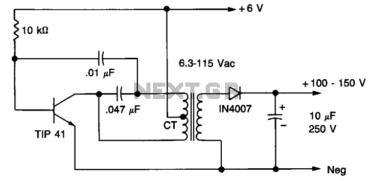
A 6 V battery can provide 100-150 Vdc center-tapped at a high internal impedance (not dangerous though it can inflict an unpleasant jolt). A 6.3 V transformer is connected in reverse with a transistor used in a Hartley oscillator...
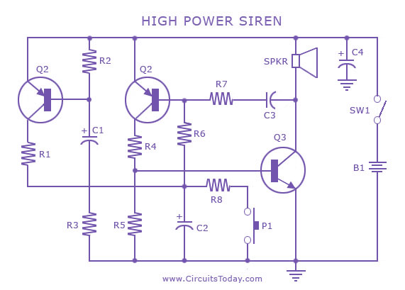
A siren circuit diagram that generates a strong, high-power siren or alarm sound using complementary transistor pairs BC 557 and BC 337, arranged as an oscillator. The described siren circuit employs a pair of complementary transistors, BC 557 (a PNP...
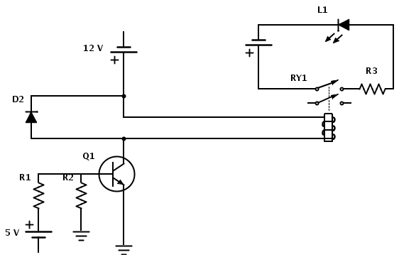
Create a circuit that enables the activation of a relay to control an LED. The relay operates at 12 V, while the available input voltage is 5 V. An NPN transistor will be utilized to switch the power to...
The project involves designing and constructing a breadboard power supply that draws power from an ATX-like switch-mode power supply (SMPS) using a 4-pin Molex connector. The design features a switch to select either a 12V or 5V output. However,...
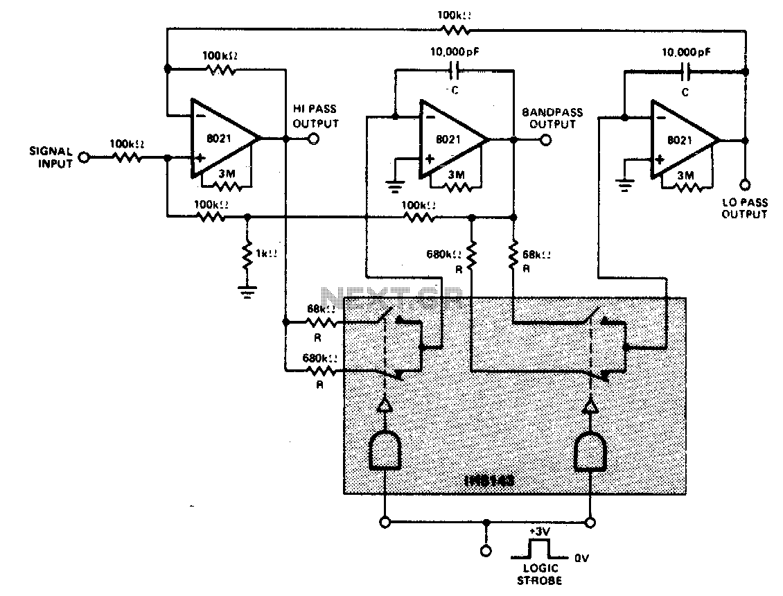
A constant gain, constant Q, variable frequency filter that provides simultaneous low-pass, bandpass, and high-pass outputs. With the specified component values, the center frequency will be 235 Hz and 23 Hz for high and low logic inputs, respectively, with...

This DC negative-voltage generator based on the 555 produces a negative output voltage equal to approximately 2 times the DC supply voltage. The described circuit utilizes the popular 555 timer IC configured in an astable or monostable mode to generate...