
Balanced Low Noise Microphone Preamp
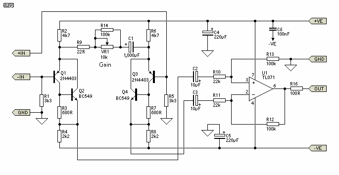
The design consists of differential compound pairs of transistors with a common mode (floating) gain control connecting the emitters of the pair. The compound pairs of 2N4403 and BC549s are far more linear than any single transistor. The circuit is differential in and out and therefore requires a balanced to unbalanced buffer to give suitable output for the next signal stages of a channel in a mixing desk. This is provided by a high performance op-amp differential gain stage, which can be a TL071 or similar IC of your choice.
The stage has a gain of six or 15 dB and that sets the maximum input level at about 1. 5 volts rms before clipping. This equals an SPL of over 150dB with a typical microphone! Full gain is 1000 times or 60dB. Distortion is low to unmeasurable because it is below the noise level at high gains. The CMRR (Common Mode Rejection Ratio) is well over 60 dB and better than any available mic cable as far as hum rejection is concerned. The bandwidth extends beyond 100kHz, and no RF suppression is shown as it has proved unnecessary in practice.
The input impedance or load on the mic is set by the two 3. 3k ohm resistors. This will suit almost any mic with a nominal impedance of 150 to 600 ohms. The input stage is configured for least noise and this has meant a non IC approach. There are some special ICs that can be used for mic pre-amps, they contain a circuit like this one except fabricated on one chip. Examples include the SSM2017 (now obsolete) or the replacement INA103 or similar. Components should all be readily available except for the 10 k ohm pot for the gain control. This needs to be a reverse log taper - or else use a multi-position switch with 6 dB gain steps covering the 60 dB range of the circuit.
Make sure it is make before break. Editor`s Note - Alternatively, a standard log pot can be used, but wired "backwards". This will work fine if it is labelled "Attenuation" instead of "Gain". As the pot is advanced clockwise, the gain is reduced (attenuation is increased). Maximum gain will therefore be applied when the pot is fully anti-clockwise. Note that this is not a problem that is specific to this circuit - all the IC mic preamps have exactly the same problem. The +/-15 Volt power supply is important too, it must be regulated and low noise. If the usual voltage regulator ICs are used I recommend fitting a post filter consisting of a 10 ohm resistor and a 470 uF capacitor to remove any noise generated in the ICs (as shown in Figure 1).
Some 7815 ICs could be sold as noise generators, the adjustable voltage ones (LM317, LM337) are very much quieter. A single regulator board may be used to power multiple preamps, with each preamp having its own post filter circuits.
Because of the extensive filtering applied, the P05 (Rev-A) power supply is recommended for this preamp. Good quality components should be used with metal film resistors in the collectors and emitters of the input pairs for least noise.
Where a resistor has significant DC voltage imposed on it in high gain circuits always use low noise types. Metal film resistors are about the best only bettered by wire wound which is a bit impractical. Avoid cermet, metal glaze, and very old carbon composition types. Also avoid bead tantalum capacitors, as they go leaky and crackle. They are just about the most fragile electronic components made. The 100nF capacitor (C6) should be mounted as close as possible to the opamp supply pins - a ceramic cap is recommended for best bypass performance at high frequencies.
The 1000uF capacitor can be a normal electrolytic of 10 or 16 volts rating. There is usually no problem with zero DC 🔗 External reference
Related Circuits
This simple stereo amplifier utilizes a National LM3871C. The pin numbers in parentheses correspond to one channel, while those without parentheses refer to the other channel. The supply voltage can range from +9 to +30 Vdc at approximately 10...
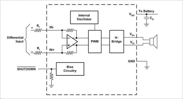
The EUA2123 is a highly efficient Class-D audio power amplifier capable of delivering up to 20W into a 4-ohm load in stereo mode using a single-ended (SE) configuration, or up to 40W into an 8-ohm load in mono mode...
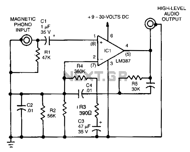
This is a collection of phono (black vinyl for the youngsters) preamps and equalisation circuits, one of which is sure to meet your requirements. These are not my circuits, but were contributed by a reader, so I am not...
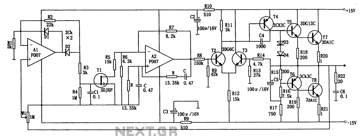
The low-frequency signal generating circuit demonstrates excellent performance characterized by stable operation, high output power, and minimal waveform distortion. It serves as an ideal source for low-frequency measurement signals. The circuit includes an operational amplifier (A) with a feedback...

In this circuit, A = 1, port = 0.5, and it features a passive vent filter without distinction. Attention is required when the circuit is dry; Q is determined by the formula Q = 1 / (3 - A)....
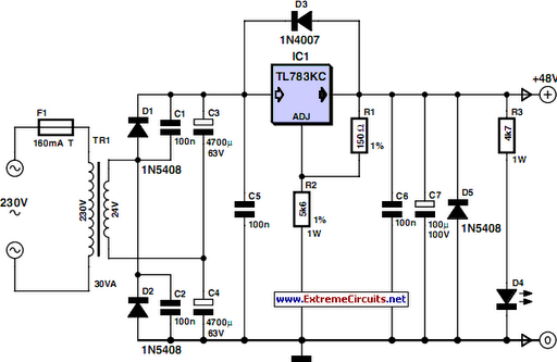
48 V phantom powering has become the standard for professional condenser microphones. The supply voltage is applied over both wires of the balanced screened cable via two 6.8 kΩ resistors. The absolute value is not critical, as a variation...