
48v phantom microphone power supply
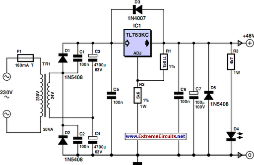
The described phantom power supply circuit is designed to deliver a stable 48 V to professional condenser microphones, ensuring optimal performance and minimal distortion. The balanced connection via 6.8 kΩ resistors allows for a consistent bias voltage across the microphone's input, crucial for maintaining audio fidelity. The design incorporates a voltage doubling rectifier, which effectively converts the 24 Vrms from the transformer into approximately 72 V DC, providing a robust supply that can accommodate fluctuations in mains voltage.
The TL783KC voltage regulator is a key component, chosen for its capability to maintain a clean output voltage with low ripple. This is particularly important in audio applications where noise can significantly impact sound quality. The use of diodes for transient protection enhances the reliability of the circuit, safeguarding against potential damage from voltage spikes.
Resistors R1 and R2 are critical for setting the output voltage, and their precise tolerances ensure that the power supply operates within the required parameters. The inclusion of a minimum load resistor, R3, is a design consideration that prevents the output voltage from sagging when the load is light, ensuring that the microphones receive a consistent voltage, which is vital for their performance.
The thermal management of the TL783KC is also an essential aspect of this design. The requirement for a heatsink with low thermal resistance indicates that the regulator will dissipate some power, and proper heat dissipation is necessary to maintain its operational integrity and longevity.
Overall, this phantom power supply circuit is a well-engineered solution for powering condenser microphones, balancing efficiency, reliability, and audio quality.48 V phantom` powering has become the standard for professional condenser microphones. The supply (or rather bias) voltage is applied over both wires of the balanced screened cable via two 6k8 resistors (see reference [1]) the absolute value is not critical, since a variation of ±20% is permitted, but they must be matched to an accuracy of 0. 4% or better [2]. Many microphones are fitted with an output transformer, and derive their power from a center-tap on the secondary. If the currents supplied by the two wires of the balanced line, which flow in opposite directions through the two halves of the secondary winding, are not identical, the magnetic fluxes they induce in the core of the transformer do not cancel out properly, and spurious magnetization occurs, causing distortion and a reduction in the microphone`s dynamic range.
With an output current of 0. 4 A, the PSU described in this article can supply` at least 40 microphones. The mains voltage is applied to a 30 VA transformer which supplies 24 Vrms. Its secondary feeds a voltage doubling rectifier formed by diodes D1 and D2 and capacitors C3 and C4. Capacitors C1 and C2 suppress the switching noise produced by the rectifier diodes. This voltage-doubling rectifier provides around 72 V DC, and so offers an adequate margin to allow for ±10% fluctuations in the mains voltage.
Voltage regulation is taken care of by TL783KC regulator IC1 on which an abundant amount of information may be found at [3]. Basically, this is an adjustable regulator in a TO220 package that offers excellent residual ripple and low noise on its output voltage.
The TL783KC regulator includes a MOS series pass transistor and accepts an input voltage of up to 125 V, making it an ideal candidate for this application. Diodes D3 and D5 respectively protect the PSU against transients at switch-off and reversed polarity.
The output voltage is set by resistors R1 and R2 according to the formula: where reference voltage Vref = 1. 27 V. These resistors should preferably have a tolerance of 1%, and R2 is likely to dissipate 0. 5 W. Resistor R3 provides a minimum load that is vital for maintaining the PSU`s off-load voltage at 48 V, and is also used to supply LED D4.
If the LED is not used, R3 must without fail be connected to ground. Last but not least, regulator IC1 must be mounted on a heatsink with a thermal resistance of less than 1. 5 °C/W using the standard insulating kit: top-hat insulating washer, mica washer, and heat sink compound.
make sure you use enough, but not too much! 🔗 External reference
Related Circuits
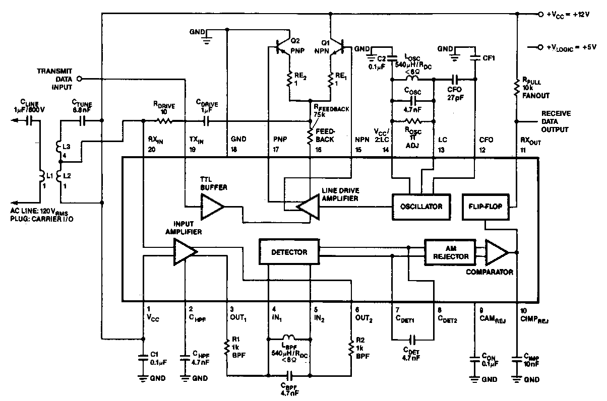
In the 100 kHz application, the coupling network connects to the receiver section located at the bottom of the chip. The external components will be summarized later. The receive data output is pulled up through a resistor (RPuLL) valued...
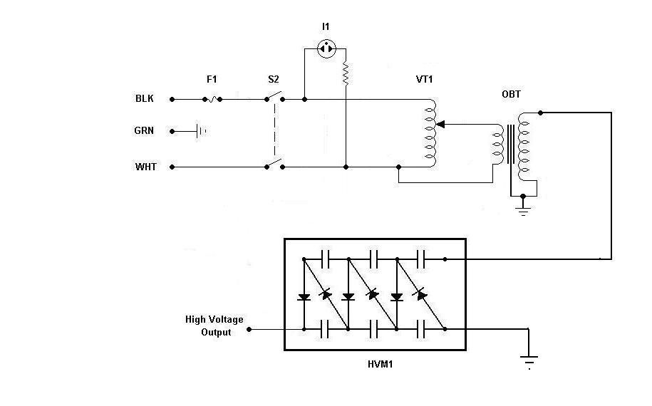
Using components from old microwave ovens, TV sets, and oil burners, it is possible to construct an economical instrument capable of producing high voltage outputs. The primary element in this setup is a voltage multiplier, which should be assembled...
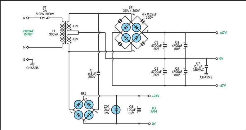
This circuit utilizes a MOSFET amplifier as the primary component for boosting audio signals. It is designed to drive a speaker with an impedance of 8 Ohms and a power output exceeding 200W. Additionally, a suitable power supply circuit...
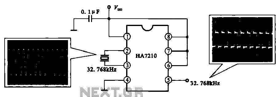
This circuit illustrates a 32.768 kHz micro-power clock oscillator, suitable for use in mobile phones, laptop computers, and home appliances. It generates a clock signal that can be utilized in various applications. The 32.768 kHz micro-power clock oscillator circuit is...

Dual power for each load refers to the operation of two power supplies working simultaneously to handle the electrical load. In the event of a power outage, a contact switch automatically closes all load circuits that are not powered...
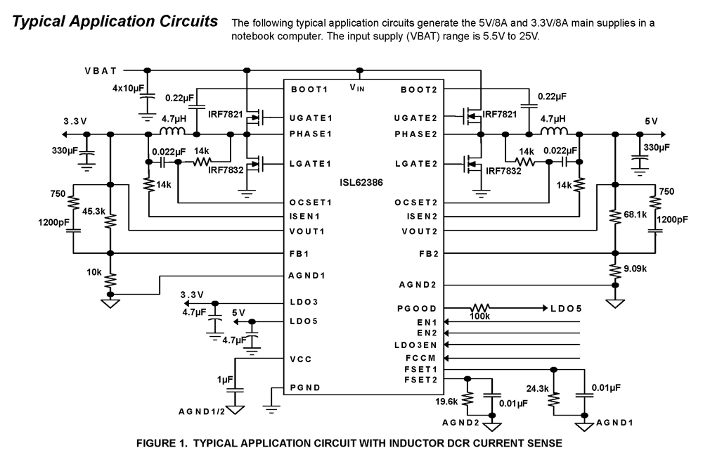
The ISL62386 controller generates supply voltages for battery-powered systems. It features two pulse-width modulation (PWM) controllers that are adjustable from 0.6V to 5.5V, along with two linear regulators, LDO5 and LDO3, which provide fixed outputs of 5V and 3.3V,...
Warning: include(partials/cookie-banner.php): Failed to open stream: Permission denied in /var/www/html/nextgr/view-circuit.php on line 713
Warning: include(): Failed opening 'partials/cookie-banner.php' for inclusion (include_path='.:/usr/share/php') in /var/www/html/nextgr/view-circuit.php on line 713