
Bandpass Filter schematic

Center Frequency = Square Root of (Lower Frequency * Upper Frequency)
The quality factor, or Q of the filter is a measure of the distance between the upper and lower frequency points and is defined as (Center Frequency / BW) so that as the passband gets narrower around the same center frequency, the Q factor becomes higher. The quality factor represents the sharpness of the filter, or rate that the amplitude falls as the input frequency moves away from the center frequency during the first octave. As the frequency gets more than one octave away from center frequency the rolloff approaches 6 dB per octave regardless of Q value. Approximate rolloff rates for different Q values for a single octave change from center frequency are:
Q = 1 = 6 dB
Q = 5 = 18 dB
Q = 10 = 24 dB
Q = 50 = 40 dB
For a single op-amp bandpass filter with both capacitors the same value, the Q factor must be greater than the square root of half the gain, so that a gain of 98 would require a Q factor of 7 or more.
The example below shows a 1700 Hz bandpass filter with a Q of 8 and a gain of 65 at center frequency (1700 Hz). Resistor values for the filter can be worked out using the three formulas below. Both capacitor values need to be the same for the formulas to work and are chosen to be 0.01uF which is a common value usable at audio frequencies. This same filter is used in the "Whistle On / Whistle Off" relay toggle circuit.
R1 = Q / (G*C*2*Pi*F) = 8/(65 * .00000001 * 6.28 * 1700) = 1152 or 1.1K
R2 = Q / ((2*Q^2)-G)*C*2*Pi*F) = 8/((128-65) * .00000001 * 6.28 * 1700) = 1189 or 1.2K
R3 = (2*Q) / (C*2*Pi*F) = 16 / (.00000001 * 6.28 * 1700) = 150K
A bandpass filter is a critical component in various electronic applications, particularly in audio processing and communication systems. It allows signals within a specific frequency range to pass while attenuating frequencies outside this range. The design of a bandpass filter involves selecting appropriate values for resistors and capacitors to achieve the desired center frequency and quality factor (Q).
In the provided example, the design targets a center frequency of 1700 Hz with a Q factor of 8 and a gain of 65. The choice of capacitors at 0.01 µF is suitable for audio applications, ensuring that the filter operates effectively within the audible range.
The calculations for resistor values (R1, R2, and R3) are derived from standard formulas that relate the Q factor, gain, capacitance, and frequency. R1 is calculated based on the gain and Q factor, ensuring that the filter can amplify signals effectively. R2 takes into account the relationship between Q, gain, and the bandwidth of the filter, while R3 is determined by the overall Q factor and the frequency, ensuring that the filter's response is sharp and well-defined.
The resulting resistor values of approximately 1.1 kΩ for R1, 1.2 kΩ for R2, and 150 kΩ for R3 illustrate the careful balance needed in the design to achieve the desired frequency response. This bandpass filter can be effectively utilized in applications such as audio signal processing, where specific frequency bands need to be isolated for further manipulation or analysis.A bandpass filter passes a range of frequencies while rejecting frequencies outside the upper and lower limits of the passband. The range of frequencies to be passed is called the passband and extends from a point below the center frequency to a point above the center frequency where the output voltage falls about 70% of the output voltage at the center frequency.
These two points are not equally spaced above and below the center frequency but will look equally spaced if plotted on a log graph. The percentage change from the lower point to the center will be the same as from the center to the upper, but not the absolute amount.
This is similar to a musical keyboard where each key is separated from the next by the same percentage change in frequency, but not the absolute amount. The filter bandwidth (BW) is the difference between the upper and lower passband frequencies. A formula relating the upper, lower, and center frequencies of the passband is: Center Frequency = Square Root of (Lower Frequency * Upper Frequency) The quality factor, or Q of the filter is a measure of the distance between the upper and lower frequency points and is defined as (Center Frequency / BW) so that as the passband gets narrower around the same center frequency, the Q factor becomes higher.
The quality factor represents the sharpness of the filter, or rate that the amplitude falls as the input frequency moves away from the center frequency during the first octave. As the frequency gets more than one octave away from center frequency the rollof approaches 6 dB per octave regardless of Q value.
Approximate rolloff rates for different Q values for a single octave change from center frequency are: Q = 1 = 6 dB Q = 5 = 18 dB Q = 10 = 24 dB Q = 50 = 40 dB For a single op-amp bandpass filter with both capacitors the same value, the Q factor must be greater than the square root of half the gain, so that a gain of 98 would require a Q factor of 7 or more. The example below shows a 1700 Hz bandpass filter with a Q of 8 and a gain of 65 at center frequency (1700 Hz).
Resistor values for the filter can be worked out using the three formulas below. Both capacitor values need to be the same for the formulas to work and are chosen to be 0.01uF which is a common value usable at audio frequencies. This same filter is used in the "Whistle On / Whistle Off" relay toggle circuit. R1 = Q / (G*C*2*Pi*F) = 8/(65 * .00000001 * 6.28 * 1700) = 1152 or 1.1K R2 = Q / ((2*Q^2)-G)*C*2*Pi*F) = 8/((128-65) * .00000001 * 6.28 * 1700) = 1189 or 1.2K R3 = (2*Q) / (C*2*Pi*F) = 16 / (.00000001 * 6.28 * 1700) = 150K
🔗 External reference
Related Circuits
The entire remote control is managed by a PIC that oversees the GSM/GPRS module's operations, monitors room temperature via a Dallas DS1820 smart probe, controls the logical state of two opto-isolated inputs, and sends commands to two relays. Additionally,...
This circuit generates dual-tone bell ringing similar to most doorbell units. It can be used in various applications beyond just doorbells. Several options will be provided in the notes to accommodate different needs. The circuit, as depicted in the...
This document contains a collection of schematic diagrams, datasheets, images, and tips for switch mode power supplies (SMPS) utilizing the TL494, LM339, KA7500, and IC2003 integrated circuits. Switch Mode Power Supplies (SMPS) are crucial components in modern electronic devices, providing...
These are plans for an EMP generator. It utilizes flash circuits from disposable cameras to power the coil. An instructable will be created soon. The EMP generator design described involves utilizing the high-voltage flash circuits found in disposable cameras. These...
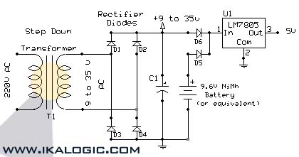
This circuit supplies electric power from a backup battery when AC power is interrupted, ensuring a stable 5V power supply for sensitive devices such as microcontrollers and logic circuits. The capacitor C1 should have a capacitance greater than 220...
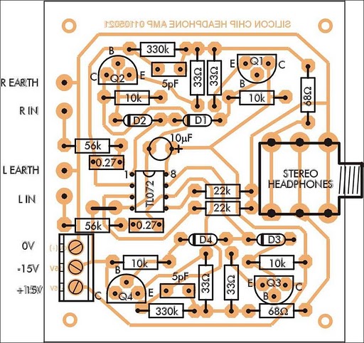
In addition to its primary function as a headphone amplifier, this circuit can be utilized for various applications requiring a wide bandwidth low-power amplifier. It is designed around an operational amplifier (op-amp), with its output current enhanced by a...